
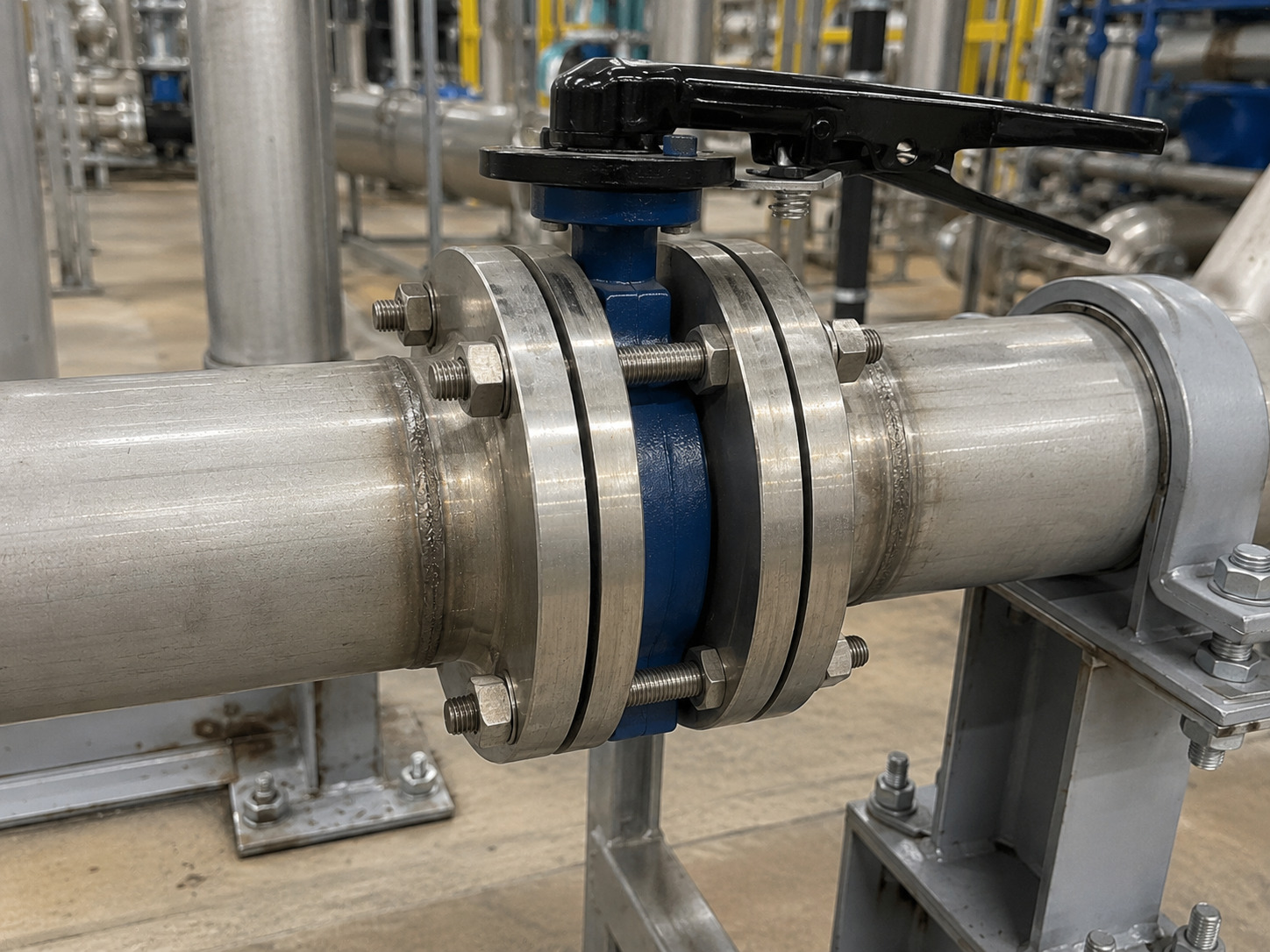
A butterfly valve wafer type is a sound choice when both pipe flanges support the valve, both sides can be isolated and depressurized for maintenance, and the materials and pressure-temperature rating match the service. Its compact body can reduce weight, space, and installed cost, but those benefits disappear if the disc hits the pipe bore, the seat is compressed incorrectly, or the line needs one-sided maintenance.
For an industrial project, selecting the word “wafer” is only the beginning. You still need to confirm the connection, shutoff duty, media, flange geometry, bolting, operating torque, and acceptance records. RUITO’s industrial butterfly valve range shows how connection style fits into a wider specification that also includes body construction, seat material, pressure class, and actuation.
What Makes a Wafer Butterfly Valve Different?
A wafer butterfly valve is a quarter-turn valve with a short body held between two pipe flanges by through-bolts or studs. The rotating disc controls or isolates flow, while the adjacent flanges provide the clamping force that keeps the valve centered and seals the body-to-flange interfaces.
The body may have centering holes or guide features, but these are not the same as a full set of threaded lugs. In most wafer installations, the fasteners span the flange-valve-flange assembly. That structural detail explains both the design’s efficiency and its main limitation: the valve normally depends on piping support from both sides.
The disc also remains inside the flow path when the valve is open. This gives the valve a short face-to-face dimension, but it means you must check pressure loss, disc clearance, and control behavior rather than treating it like an unobstructed pipe spool.
Choose Wafer Only When the Maintenance Plan Allows It
Wafer style is usually the better body choice for compact inline service where the whole section can be isolated, drained, and depressurized before nearby piping is removed. Lug or double-flanged construction deserves review when the valve must remain attached to one flange, serve at the end of a line, or support sectional maintenance.
This table connects body style to the operating decision it changes.
| Decision point | Wafer body | Lug body | Double-flanged body |
|---|---|---|---|
| Mounting | Clamped between two flanges | Each flange bolts to threaded body lugs | Integral valve flanges bolt to pipe flanges |
| Normal maintenance assumption | Isolate and depressurize both sides | One-side removal may be possible if rated | Suitable for permanent, structurally robust connections |
| Typical advantage | Lower body weight and short face-to-face length | More flexible isolation and maintenance | Strong alignment and large-size suitability |
| Critical verification | Through-bolt fit and disc clearance | Dead-end pressure rating and thread engagement | Face-to-face length, support, and flange match |
The important word is rated. A lug body is not automatically approved for full-pressure dead-end service. Its allowable differential pressure may be lower in that condition, and the permitted pressure direction may matter. Obtain the model-specific dead-end statement instead of approving the valve from the connection name alone. A detailed wafer-versus-lug comparison can help when the shutdown strategy is the deciding factor.
Confirm the Flange Interface Before You Confirm Size
Nominal pipe size alone cannot prove that a wafer valve will fit. Confirm the flange standard, pressure class, bolt circle, bolt quantity and diameter, flange inside diameter, face type, required stud length, and the valve’s face-to-face dimension against the manufacturer drawing.
Disc clearance is especially important. A valve can match the bolt circle while its open disc interferes with a small-bore flange, pipe liner, weld bead, or nearby fitting. Compare the maximum disc sweep with the actual clear bore on both sides. If the valve is replacing an installed unit, record the old face-to-face length and measure the accessible bore instead of relying only on the nameplate size.
Bolting also changes with the flange system and valve body geometry. The purchase package should identify stud or bolt diameter, length, material, quantity, and any fasteners that must clear the body neck or actuator bracket. Use the project piping class for the final fastener material and coating; a generic bolt chart cannot account for corrosion exposure or project-specific flange faces.
Match the Seat and Trim to the Actual Service
Seat and trim selection must follow the medium, concentration, temperature, maximum differential pressure, solids content, cleaning chemicals, and cycling frequency. “Water service” or “chemical service” is too broad for final material approval.
EPDM is commonly considered for water and HVAC duties that do not contain hydrocarbons. NBR may suit certain oil-related services, while PTFE is often selected when broader chemical resistance is needed. Metal seating may be required for temperatures or abrasive conditions beyond elastomer limits. These are starting directions, not blanket approvals; check a reliable compatibility source for the exact compound and fluid mixture. For a deeper material review, use the butterfly valve seal selection guide.
The same discipline applies to the disc, stem, body, and coating. RUITO’s current butterfly valve portfolio lists ductile and cast iron, carbon and stainless steel, duplex options, and EPDM, NBR, PTFE, FKM, and metal seating across the broader range. The approved combination and rating remain configuration-dependent, so the quotation and drawing should identify the actual materials for every pressure-retaining and wetted part.
Size the Operator for Duty, Not Handle Preference
The operator must be sized for the valve’s required torque at the worst credible operating condition, not merely for nominal pipe size. Request breakaway, running, and seating torque data at the maximum differential pressure, then account for seat material, temperature, media deposits, operating frequency, and the required actuator margin.
A lever is practical on smaller valves that are accessible and operated infrequently. A gearbox reduces manual effort on larger sizes or higher-torque duties. Pneumatic and electric actuators add remote operation, position feedback, and control functions, but the mounting interface, stem dimensions, travel stops, failure position, speed, enclosure, and power or air supply must all be specified.
Throttling requires a separate check. Butterfly valves can regulate flow, but stable control depends on the valve’s Cv curve, operating angle, pressure drop, cavitation or noise risk, and dynamic torque. If the valve will spend long periods close to the shut position, high local velocity can accelerate seat or disc-edge wear. Size the valve for the intended control range rather than automatically matching line size.
Install the Valve Without Distorting the Seat
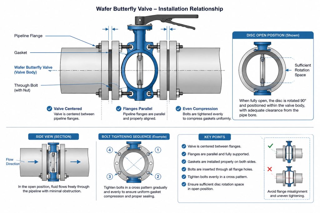
Correct installation keeps the body centered, the flange faces parallel, and the disc free to rotate before final tightening. Clean the flange faces and pipe bore, support the piping independently, and never use the valve to pull misaligned flanges into position.
Many resilient-seated wafer valves do not use separate flange gaskets because the seat faces provide the external seal. Adding an unapproved gasket can change compression, raise operating torque, or damage the liner. This is not a universal no-gasket rule: follow the installation instructions for the exact valve and flange face.
Use this sequence to reduce installation risk:
- Verify that the valve tag, drawing, flange class, materials, and flow-direction marking match the line.
- Position the disc nearly closed so its edge stays inside the body while the valve is inserted.
- Center the valve, install all fasteners hand-tight, and open the disc fully to confirm bore clearance.
- Tighten fasteners gradually in a cross pattern so flange compression remains even.
- Cycle the valve through its full travel and confirm that torque is smooth before pressurization.
- Perform the specified shell, external-joint, and seat checks under the approved startup procedure.
If the disc rubs, torque rises sharply, or the body shifts during tightening, stop and correct the flange alignment or bore mismatch. The wafer-valve fit and installation checks cover these interface risks in more detail.
Approve the Valve With Evidence, Not a Model Number
A valve should be released for manufacture or shipment only after its documents prove fit, materials, shutoff performance, and operator compatibility. A model number without a controlled drawing and bill of materials leaves too many project decisions implicit.
Use this approval package before you sign off the order.
| Approval item | What it should confirm | Risk it controls |
|---|---|---|
| General arrangement drawing | Face-to-face, disc sweep, flange match, stem and operator envelope | Site interference and rework |
| Bill of materials | Body, disc, stem, seat, coating, and fasteners | Media or temperature mismatch |
| Torque data and operator sheet | Maximum differential, required torque, selected operator output, travel and failure position | Stalling or incomplete shutoff |
| Pressure and leakage procedure | Test pressure, duration, medium, acceptance criterion, and valve orientation | Unverified pressure integrity |
| Material and inspection records | Heat or batch traceability, dimensional checks, coating records, and test results | Substitution and inconsistent lots |
| Bolting schedule | Quantity, diameter, length, material, and installation notes | Assembly delay and poor clamping |
The package should be specific to the supplied configuration and linked to the valve or batch identification. RUITO’s published QC flow includes material certificates, dimensional inspection reports, torque logs, hydrostatic test charts, leakage certificates, and pre-shipment release records. Its product page currently identifies common stock wafer configurations as DN50-DN600, PN10/PN16, with ductile iron bodies and EPDM or NBR seats; availability and suitability still require order-specific confirmation.
Know Where Wafer Style Fits and Where It Does Not
Wafer valves fit water distribution, wastewater, HVAC loops, cooling water, compressed air, irrigation, and many general utility lines when full-section isolation is practical. Their compact body is particularly useful in mechanical rooms and skid piping where space and support loads matter. RUITO’s water and wastewater valve applications show how media, solids, cycling, and actuator duty change the specification across one industry.
Do not select a standard resilient-seated wafer valve by default for severe slurry, high temperature, aggressive corrosion, chronic cavitation, frequent near-closed throttling, or safety-critical terminal isolation. Those conditions may call for a different seat, offset geometry, material package, body connection, or valve type.
The commercial advantage is therefore conditional: a wafer valve reduces installed complexity only when the piping can support it, the shutdown plan accepts it, and the selected internals can survive the duty.
Specify the Connection Before You Request the Valve
A butterfly valve wafer type is a practical industrial choice when you verify the complete flange-valve-flange assembly instead of buying from nominal size and pressure class alone. Confirm maintenance isolation, flange geometry, disc clearance, material compatibility, operating torque, bolting, and acceptance documents before release.
For a project review or quotation, send RUITO your line data and drawings with the medium, pressure, temperature, flange standard, size, operation method, quantity, and required test documentation. That information lets the engineering team check whether wafer, lug, or flanged construction is the correct starting point.
FAQ
Can a wafer butterfly valve be installed vertically?
Yes, many wafer butterfly valves can be installed in vertical piping, but the exact model and service must permit it. Check the preferred stem orientation, support a heavy actuator independently where required, and consider how solids or condensate may collect around the disc and seat.
Does flow direction matter on a wafer butterfly valve?
It can. Some concentric resilient-seated designs are bidirectional, while offset or application-specific valves may have a preferred pressure direction. Follow the body arrow, data sheet, and test orientation for the supplied model rather than assuming that every wafer valve seals equally in both directions.
Can I replace a lug valve with a wafer valve of the same size?
Only after a new connection and maintenance review. Matching nominal size does not preserve dead-end capability, one-side pipe removal, bolting, face-to-face length, disc clearance, or actuator envelope, so verify the complete assembly before approving the substitution.