
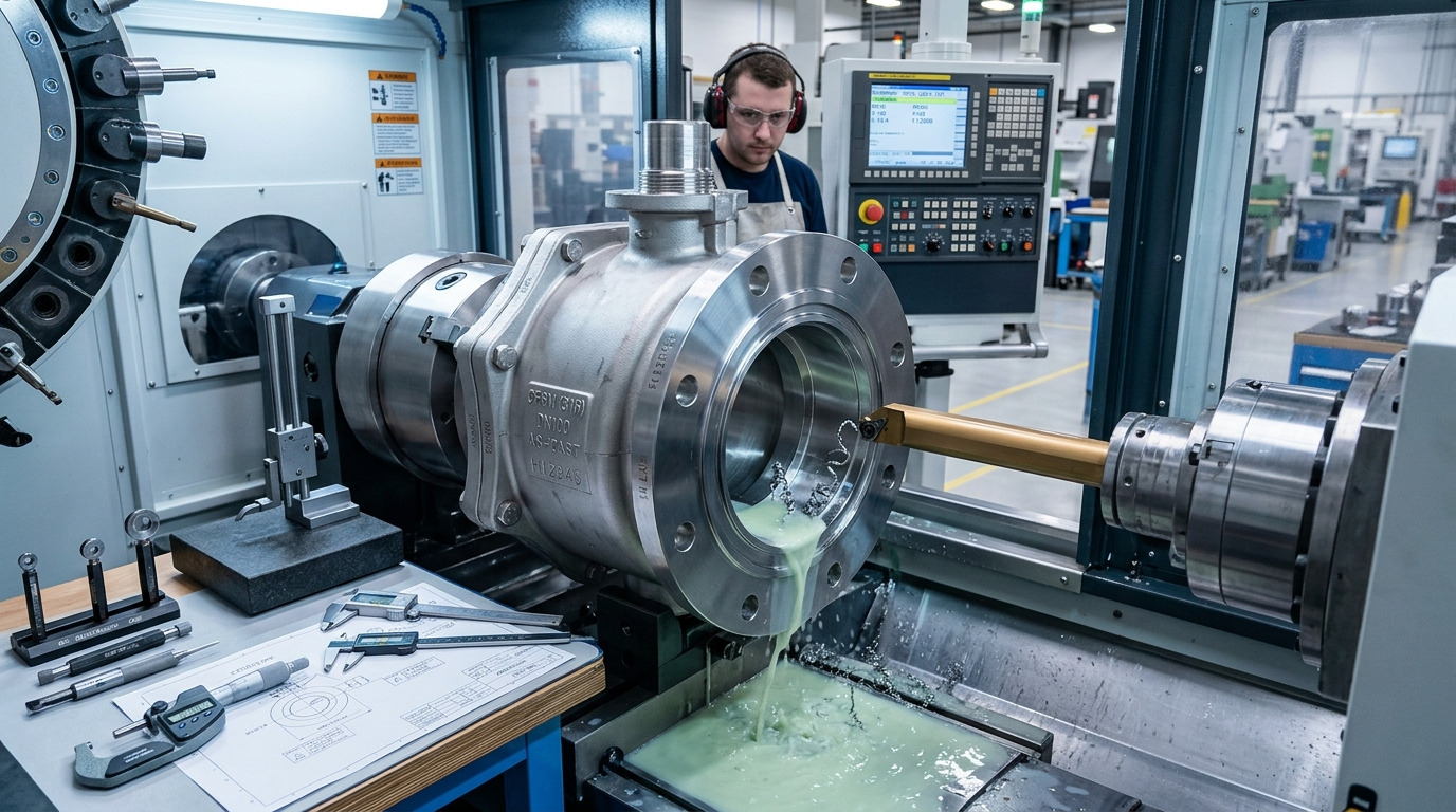
The ball valve manufacturing process is a controlled sequence that turns material selection, precision machining, assembly, and pressure testing into a valve suited to a defined service condition. When two valves look similar on a datasheet, the real risk often sits inside the body material, ball finish, seat design, stem sealing, flange interface, and test requirements.
For engineers, OEM buyers, and project procurement teams, understanding this process helps prevent a common problem: ordering a valve that fits the product name but not the operating duty. If you are comparing construction types and applications, RUITO’s industrial ball valves page gives product-level context while this article explains how the manufacturing steps affect quality, fit, and specification risk.
What the Process Must Prove Before Production
A reliable process must prove that the valve can match the service conditions, not just that it can be assembled. Before metal is cut, the manufacturer needs a clear basis for body material, bore type, pressure-temperature rating, end connection, seat material, stem sealing, actuation, and testing.
A ball valve is simple in operation: a rotating ball opens or blocks the flow path. Manufacturing is less simple because small variations in seat pocket geometry, ball roundness, stem alignment, surface finish, or seal compression can change leakage behavior and operating torque. That is why the manufacturing route should start from the application, then move into drawings, materials, production controls, and final verification.
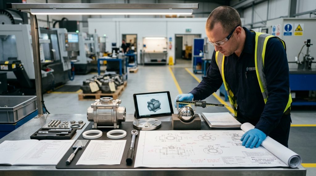
The first practical question is not “How is the valve made?” but “What must this valve survive?” Clean water, gas isolation, chemical transfer, thermal oil, slurry, and steam impose different limits on material, seat, stem packing, and test language. A good process keeps those limits visible from the first quotation through final marking.
The Ball Valve Manufacturing Process by Stage
The ball valve manufacturing process usually follows a staged path: specification review, raw material control, casting or forging, machining, ball finishing, seat and seal preparation, assembly, pressure testing, marking, and packaging. The exact route changes with valve size, body design, material, and project standard, but the quality logic is consistent.
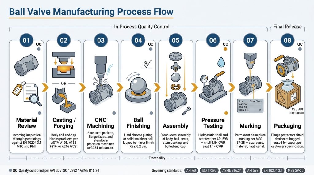
Raw component forming
Bodies, end caps, and other pressure-containing parts may be cast, forged, or fabricated depending on the valve design and specification. Carbon steel cast bodies are commonly tied to material standards such as ASTM A216/A216M-26, which covers carbon steel castings for valves, flanges, fittings, and other pressure-containing parts, including grades WCA, WCB, and WCC.
For stainless or corrosion-resistant service, the casting route may follow a different specification. ASTM A351/A351M-24E01 covers austenitic steel castings for valves, flanges, fittings, and pressure-containing parts, and it makes clear that grade selection depends on design and service conditions.
Machining and ball finishing
Machining turns the raw body into a controlled pressure component. The internal bore, seat pockets, stem hole, end connections, sealing faces, and mounting surfaces must match the drawing because these features decide whether the valve can be assembled without forcing the seat or misaligning the stem.
The ball itself needs accurate geometry and a suitable surface finish. A rough or poorly rounded ball can increase friction, damage soft seats, or create inconsistent sealing contact. Coating, plating, or hard-facing may be used when the service requires corrosion resistance, lower friction, or better wear behavior, but the choice must match the fluid and temperature.
Assembly and functional checks
Assembly brings together the body, ball, seats, seals, stem, packing, body joints, handle, gearbox, or actuator interface. This is where machining quality becomes visible. If the seat pocket is too loose, the seat may shift; if compression is excessive, torque can rise; if the stem sealing system is poorly controlled, external leakage risk increases.
At this stage, manufacturers may check operation, torque feel, travel stop position, handle orientation, and basic closure function before pressure testing. The goal is not to make the valve look complete; it is to confirm that the moving and sealing parts work together within the intended design.
Materials and Seats Define the Manufacturing Route
Material and seat selection shape the entire manufacturing route because they determine casting method, machining behavior, surface treatment, assembly compression, and test expectations. A valve body material that is acceptable for one fluid can be unsuitable for another, even when the pressure rating looks adequate.
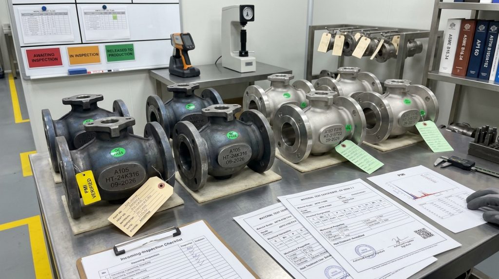
Carbon steel, stainless steel, duplex alloys, brass, bronze, and special alloys all have different corrosion, strength, and cost profiles. The choice should be based on media chemistry, temperature, pressure, corrosion allowance, cleaning procedure, and project standard. In chemical service, this decision often becomes more important than the valve type itself.
Seat material is just as critical. Soft seats such as PTFE-based materials can support low-friction operation and tight closure in compatible clean service, but they can be limited by heat, abrasive particles, pressure load, swelling, or creep. If seat behavior is a major concern, the service discussion should include actual media, concentration, temperature, pressure, cycling frequency, and whether a ball valve PTFE seat is appropriate or whether another sealing strategy is safer.
Metal seats may be considered for abrasive, high-temperature, or severe service conditions, but they are not a universal upgrade. They can require harder ball surfaces, tighter finishing control, higher operating torque, and a different leakage expectation under the specified test class.
Machining Controls the Seal, Torque, and Fit
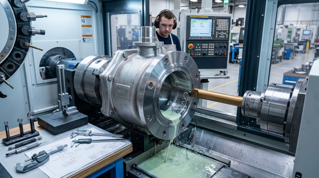
Precision machining is where a ball valve becomes either a controlled sealing device or a future field problem. The body cavity, seat pockets, ball bore, stem slot, packing chamber, flange faces, and threaded or welded ends must align with the drawing and the intended assembly sequence.
Seat pockets and sealing faces
Seat pockets control how the seat is supported under pressure. If the pocket geometry allows too much movement, a soft seat can deform or extrude. If the seat is over-compressed, the valve may become difficult to operate, especially after storage or thermal cycling.
Sealing faces also need proper finishing. A flange face, body joint, or packing contact surface that looks acceptable from a distance may still create sealing risk if the surface profile is not suitable for the gasket or seal design. This is why dimensional checks should happen during machining, not only after the full batch is completed.
Bore, ball, and stem alignment
Full bore and reduced bore are not only flow labels; they affect machining, ball size, weight, cost, and pressure loss. A full-bore valve can be valuable where low restriction or pigging is required, while a reduced-bore design may be acceptable where some pressure loss is allowed. For flanged designs, the end connection must also match the piping specification, so readers reviewing flange class and interface details may need a separate check on flanged ball valve selection.
Stem alignment affects torque and sealing. A misaligned stem can load the ball unevenly, damage the seat, or make actuation less predictable. In automated packages, this matters because actuator sizing depends on realistic valve torque, not only nominal valve size.
Assembly Converts Parts Into a Valve Package
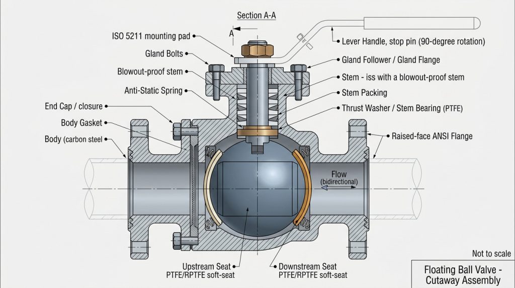
Assembly converts machined components into a pressure-containing, operating valve package. The assembly process must control cleanliness, seal placement, fastener tightening, stem packing compression, ball orientation, and actuator or handle alignment.
Floating and trunnion construction
Floating and trunnion-mounted ball valves are assembled differently because the pressure load moves through the valve differently. In a floating design, line pressure pushes the ball toward the downstream seat. In a trunnion-mounted design, the ball is mechanically supported, and the seats are usually spring-energized or otherwise loaded against the ball.
This difference changes seat loading, torque behavior, cavity relief considerations, and actuation planning. When large size, higher pressure, or pipeline isolation is involved, the design review should look beyond the product name and compare trunnion ball valve vs floating selection before confirming the manufacturing route.
End connections and actuation
End connections are assembled and checked according to the valve design: threaded, flanged, socket weld, butt weld, or other project-specific ends. For flanged valves, the connection is part of the mechanical interface with the piping system, not a cosmetic feature. ASME B16.5-2025 covers pipe flanges and flanged fittings from NPS 1/2 through NPS 24 and includes pressure class designations such as 150, 300, 400, 600, 900, 1500, and 2500 within its stated scope.
If the valve is automated, the assembly also needs a compatible mounting interface, stem drive arrangement, and torque basis. A good package review asks how the valve will operate under pressure differential, after inactivity, and under the specified seat material, rather than assuming all valves of the same size require the same actuator.
Testing and Documentation Close the Quality Loop
Testing and documentation close the loop by connecting the manufactured valve back to the original specification. A valve should not be treated as complete until pressure-boundary integrity, closure behavior, marking, and required documents are checked against the purchase requirements.
The table below helps buyers connect manufacturing stages with the standards or checks that often belong in a technical review.
| Review area | What it helps control | Useful standard or verification point |
|---|---|---|
| Valve construction | Pressure-temperature basis, materials, dimensions, tolerances, NDE, testing, and marking | ASME B16.34-2025 applies to new flanged, threaded, welding-end, and related valve construction within its scope |
| Flanged interface | Flange size, class, facing, bolting, gasket, and joint compatibility | ASME B16.5-2025 defines the stated NPS and class scope for flanges and flanged fittings |
| Carbon steel castings | Casting grade selection for pressure-containing valve parts | ASTM A216/A216M-26 covers carbon steel castings for valves, flanges, fittings, and related pressure parts |
| Austenitic steel castings | Stainless casting selection for high-temperature or corrosion-related service | ASTM A351/A351M-24E01 covers austenitic steel castings for pressure-containing valve parts |
| Pressure testing | Pressure-boundary integrity, closure tightness, and closure mechanism adequacy | ISO 5208:2015 specifies examinations and tests for industrial metallic valves |
| Fugitive-emission type testing | External leakage evaluation at stem seals or body joints for volatile or hazardous fluids | ISO 15848-1:2015 covers type-testing classification procedures and excludes end connection joints, vacuum application, corrosion effects, and radiation |
The table does not replace the project specification. It shows why a purchase order should name the applicable standard, edition, material, test requirement, and documentation expectation instead of relying on a broad description such as “industrial ball valve.”
Pressure and closure checks
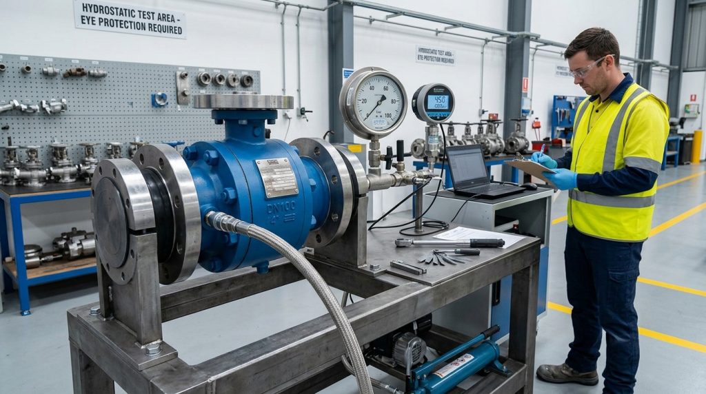
Pressure testing should be defined by the product standard, project specification, or purchaser requirement. ISO 5208:2015 is useful language for metallic industrial valves because it separates pressure-boundary integrity, closure tightness, and structural adequacy of the closure mechanism.
For hazardous or volatile fluids, seat leakage is not the only concern. Stem packing and body joints may require separate fugitive-emission evaluation, and ISO 15848-1:2015 is relevant when the project calls for that type of qualification. The important point is to specify the test basis before production, not after a valve has already been built.
Marking, packaging, and RFQ clarity
Marking should help connect the valve to its material, size, pressure class, flow direction if applicable, heat or batch traceability, and project documentation. Packaging should protect sealing surfaces, ends, coatings, and internal cleanliness during storage and transport.
A practical RFQ should include media, concentration, solids content, normal and maximum pressure-temperature conditions, pipe size, end connection, bore requirement, valve design, seat and seal materials, actuation method, applicable standards, inspection requirements, and documentation needs. These details let the manufacturer discuss a buildable valve instead of guessing from a short product name.
Conclusion
The ball valve manufacturing process is not just a factory sequence; it is a chain of decisions that starts with service conditions and ends with tested, marked, and documented equipment. Material selection, machining accuracy, ball finishing, seat design, assembly control, and pressure testing all affect whether the valve fits the real duty.
RUITO’s position is that valve quality should be discussed through specifications, service conditions, and verification steps rather than broad claims. If you are preparing a project inquiry, share your media, pressure-temperature range, size, connection standard, material preference, seat requirement, actuation needs, drawings, and test expectations through RUITO’s project consultation channel so the discussion can focus on fit, risk, and manufacturing clarity.
FAQ
What is the most important step in ball valve manufacturing?
The most important step is matching the manufacturing route to the service conditions before production begins. Good machining and testing cannot fully compensate for the wrong body material, seat material, pressure class, or end connection.
Is casting or forging better for a ball valve body?
Neither is automatically better for every valve. Casting can suit complex body geometry, while forging can suit certain strength and grain-flow expectations; the correct choice depends on size, material, pressure class, standard, cost, and the valve design.
Does a polished ball alone prove good shutoff performance?
No, the ball finish alone does not prove closure performance. Shutoff depends on ball geometry, seat material, seat support, assembly compression, stem alignment, pressure differential, temperature, and the specified test requirement.
Which standards should be named when buying ball valves?
The standards depend on the project, region, valve type, and service. Common review areas include valve construction, flange interface, material specification, pressure testing, and any required fugitive-emission qualification.
What information helps a manufacturer review the process correctly?
Send the media, pressure-temperature conditions, pipe size, end connection, bore type, body and seat material expectations, actuation method, applicable standards, inspection needs, and drawings. Clear input reduces guesswork and helps align production controls with the actual duty.