

For a 4-inch butterfly valve between ASME Class 150 flanges, the common pattern uses 5/8-11 UNC fasteners at eight flange locations, but bolt length is not universal. A wafer body normally uses eight through-bolts or studs, while a lug body commonly needs sixteen cap screws—eight from each side. The final length depends on the valve body, flange thickness, permitted gaskets, washers, nuts, and thread engagement.
That distinction prevents a familiar site problem: the ordered bolt has the correct diameter but cannot clamp the joint. Before buying hardware, identify the flange standard and pressure class, then match the fastener to the specific wafer, lug, or flanged butterfly valve configuration.
The Common 4-Inch Class 150 Answer
The usual North American answer is 5/8-11 UNC, with eight fastener locations for an NPS 4 ASME Class 150 flange pattern. This is a conditional answer, not a universal rule for every 4-inch valve.
Use the following table as a planning reference when the mating flanges and valve drilling are confirmed as ASME Class 150.
| Item | Common NPS 4 Class 150 reference |
|---|---|
| Nominal fastener diameter | 5/8 inch |
| Thread series | 11 TPI UNC |
| Flange fastener locations | 8 |
| Wafer-body fasteners | Usually 8 through-bolts or studs |
| Lug-body fasteners | Usually 16 cap screws, 8 per flange |
| Double-flanged-body fasteners | Two separate 8-bolt flange joints |
| Finished fastener length | Must be verified from the assembly stack and valve drawing |
The key purchasing conclusion is simple: diameter and count can come from the flange pattern, but length comes from the assembled joint. For adjacent NPS sizes, consult the full Class 150 bolt-pattern chart instead of extending the NPS 4 values by assumption.
Confirm the Flange Standard Before Using Any Size
The flange standard and pressure class determine the bolt circle, hole count, and nominal fastener diameter. “Four inch” identifies the valve’s nominal line size; it does not identify the connection standard.
The current ASME B16.5 standard covers dimensions, tolerances, flange bolting, gaskets, and joints for NPS 1/2 through NPS 24 across several pressure classes. An NPS 4 Class 300 joint, an ASME Class 150 joint, and a DN100 PN16 joint must therefore be treated as separate specifications. Similar nominal pipe sizes do not make their drilling patterns or threads interchangeable.
Before selecting a fastener, read these fields from the approved line class, flange marking, or drawing:
- NPS or DN size
- Flange standard and pressure class
- Flange facing and material
- Valve connection style and exact model
- Inch or metric thread system
If any one of these fields is missing, the specification is not ready for ordering. A 5/8-inch bolt and an M16 fastener may look close in diameter, but they do not share the same thread and must not be substituted in a tapped lug.
Valve Body Style Changes the Fastener Arrangement
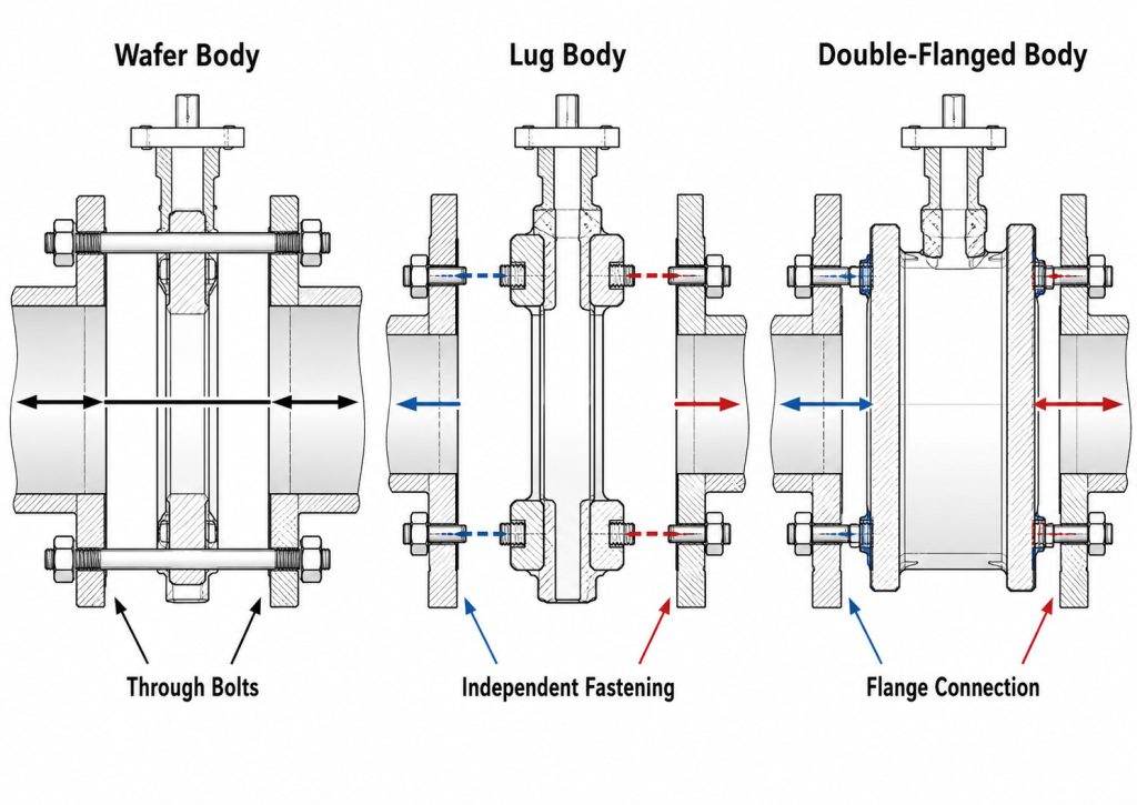
The valve body determines whether the fastener passes through the assembly, enters a tapped lug, or forms one of two conventional flange joints. This is why bolt kits for wafer and lug valves are not interchangeable even when both valves fit the same Class 150 drilling pattern.
Wafer body
A wafer valve is clamped between two pipe flanges. Its machine bolts or studs cross the full assembly, so the grip includes both flanges and the valve body at the bolt path. Nuts may be required on one or both ends depending on whether the specified fastener is a headed bolt or a stud.
Lug body
A lug valve normally has tapped body lugs and is fastened independently from each side. For the common NPS 4 Class 150 pattern, eight cap screws enter from the upstream side and eight enter from the downstream side. The cap screws must achieve the specified thread engagement without bottoming out or meeting an opposing fastener inside a through-tapped lug.
Double-flanged body
A double-flanged valve creates two separate flange joints. Each side has its own gasket rule, bolts or studs, nuts, and tightening sequence. Do not use the wafer-body width as the grip dimension for this arrangement.
If the body style is still under review, the wafer-versus-lug selection guide explains how maintenance access and end-of-line service affect the connection decision.
Calculate Bolt Length From the Actual Joint Stack
Correct bolt length is the sum of the material being clamped plus the required nut engagement or tapped-thread engagement. A generic length chart can support budgeting, but it cannot replace the valve drawing and actual flange data.
For a wafer valve with a headed through-bolt and one nut, establish the grip first:
Grip = flange 1 + valve body at bolt path + flange 2 + permitted gasket allowance + washer allowance
Then add the nut height and required thread projection to obtain the ordered under-head length. For a stud with two nuts, add the two nut allowances and the required end projections to the same grip. Round only according to the project’s approved fastener length increments; rounding down can leave incomplete nut engagement.
For a lug valve cap screw, use a different check:
Cap-screw length = flange thickness + permitted gasket allowance + washer allowance + required lug engagement
Compare that result with the usable tapped depth. A blind hole needs bottoming clearance. A through-tapped lug may also need clearance between opposing cap screws. If the drawing does not state usable depth, obtain that dimension before releasing the purchase order.
Gasket allowance cannot be assumed. Many resilient-seated designs use the seat face as the flange seal, while other butterfly valve designs require a separate gasket. Confirm the applicable butterfly valve gasket selection before adding gasket thickness to the stack.
Match the Fastener Specification to the Service
Fastener material, grade, coating, nuts, and washers must come from the piping material specification or an approved engineering review. Matching only the diameter can leave the joint with inadequate strength, corrosion resistance, temperature capability, or traceability.
Record the complete designation rather than writing “stainless bolts” or “carbon-steel bolts.” The order should identify the material standard and grade, thread series, finish or coating, nut grade, washer requirement, and any low-temperature or sour-service restrictions. If stainless fasteners are selected, the assembly procedure should also address galling and the approved lubricant.
Lubrication changes the relationship between applied torque and bolt load. Never copy a torque value from a chart that assumes a different grade, coating, nut, washer, or lubricant. The target is the specified joint load and even compression, not a familiar wrench setting.
Verify Fit-Up Before Final Tightening
Fit-up verification should prove that the selected fastener clamps the joint without pulling misaligned piping into place. Perform this work only on an isolated, depressurized line under the site’s approved safety procedure.
Start by cleaning and aligning the flange faces. Center the valve, keep the disc in the installation position stated by the valve manual, and install the fasteners finger-tight. Confirm that each bolt passes freely, each lug screw enters by hand without cross-threading, and no fastener bottoms before the flange is clamped.
Tighten in a cross pattern using progressive passes, then check disc movement before and after the final pass when the product procedure permits it. Binding, uneven seat compression, a changing flange gap, or a cap screw that reaches torque without closing the joint are stop-work signals. Correct the alignment or fastener length before pressure testing; do not use higher torque to force the assembly together.
For conventional gasketed pressure-boundary flange joints within its defined scope, ASME PCC-1 provides assembly and troubleshooting guidance. The valve manufacturer’s procedure still controls valve-specific details such as disc position, resilient-seat compression, gasket use, and acceptable torque. The wafer valve installation procedure covers the broader sequence from alignment through operational checks.
Put a Complete Bolt Callout on the Purchase Order
A complete purchase callout identifies the connection, the fastener, and the verification document. This lets procurement compare equivalent offers and gives the installer an auditable basis for fit-up.
Include the following information:
- Valve size: NPS 4 or DN100, as applicable.
- Valve manufacturer, model, body style, and drawing revision.
- Mating flange standard, class or PN rating, facing, and material.
- Fastener type: machine bolt, stud, or cap screw.
- Nominal diameter, thread series, and thread fit where specified.
- Quantity per valve and whether the count is per side.
- Under-head bolt length or overall stud length.
- Fastener and nut material standards, grades, and coatings.
- Washer and lubricant requirements.
- Gasket rule and gasket thickness when a separate gasket is permitted.
- Approved tightening procedure or target bolt-load basis.
- Required evidence: dimensional drawing, bolting schedule, material certificates, or inspection record.
Do not approve a line item described only as “4-inch butterfly valve bolt set.” That wording omits the standard, body style, length basis, and material grade—the fields most likely to cause an installation mismatch.
Order the Fasteners From Verified Dimensions
For the common NPS 4 ASME Class 150 connection, begin with 5/8-11 UNC fasteners and eight flange locations. Then use the valve body style to determine whether you need eight wafer through-fasteners, sixteen lug cap screws, or two separate eight-bolt flanged joints. Finalize length only after checking the drawing and complete assembly stack.
RUITO can review the flange standard, body configuration, gasket rule, and bolting interface for a valve order, then provide the dimensional drawing needed for approval. Send the line class, mating-flange details, valve model, and required fastener specification when you contact RUITO for a technical review.
FAQ
Can I replace a 5/8-11 bolt with an M16 bolt?
No, not without an approved redesign. The nominal diameters are similar, but the thread forms and pitches differ; an M16 fastener will not correctly engage a 5/8-11 tapped lug.
Can one long bolt pass through both sides of a lug valve?
Only when the valve drawing explicitly permits it. Most lug valves use separate cap screws from each side, and through-tapped lugs may not provide a continuous clearance path for one long fastener.
Why do 4-inch butterfly valve charts show different bolt lengths?
They may assume different valve castings, flange types, gasket thicknesses, washers, nut patterns, or fastener styles. Treat a published length as model-specific unless its stated assumptions match your complete joint.
How much thread should project beyond the nut?
Use the project bolting specification and approved assembly procedure. The projection must confirm full nut engagement without creating clearance problems, but a universal thread-count rule should not replace the specified joint design.