
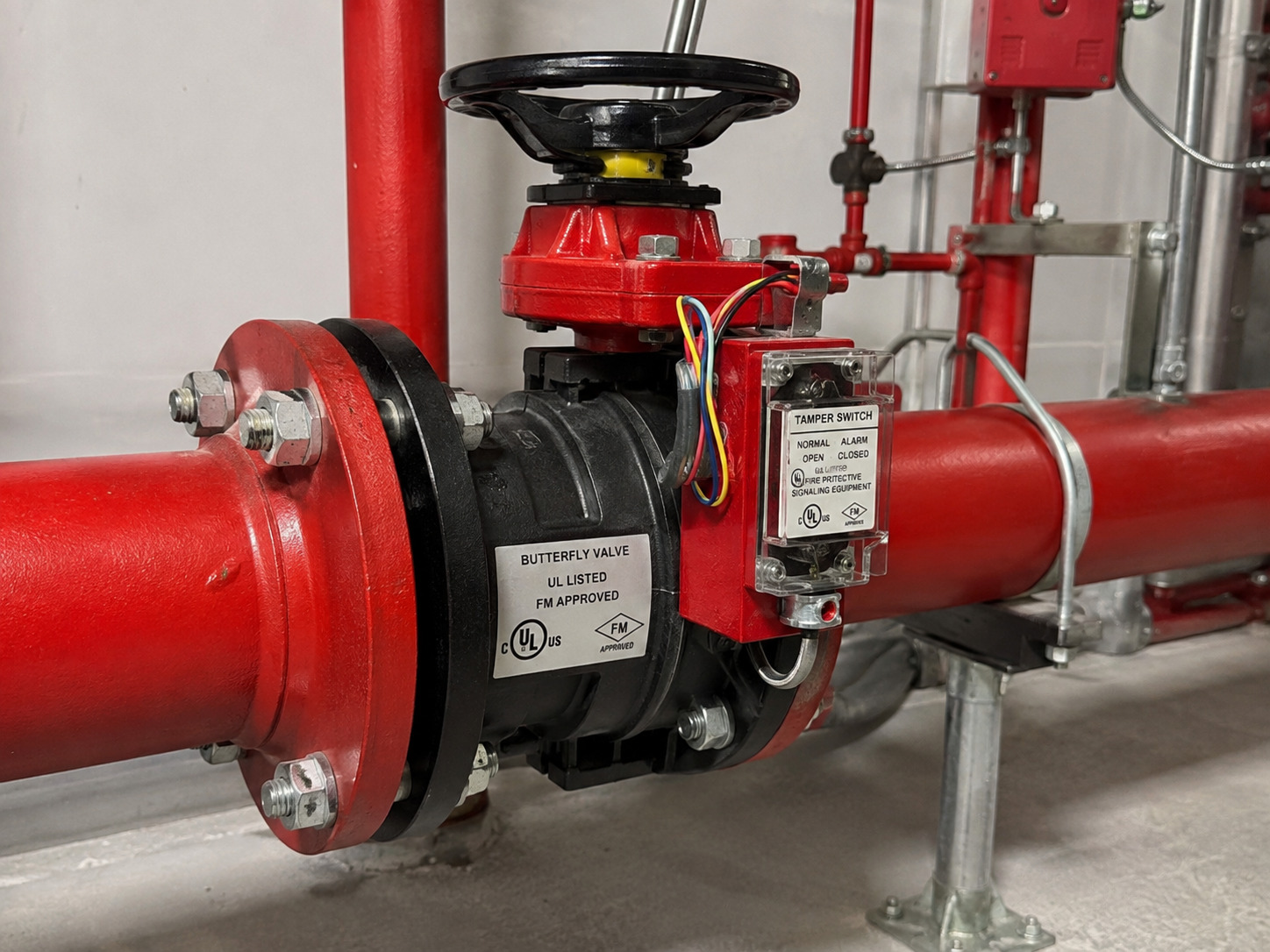
A butterfly valve tamper switch is a supervisory device that reports when a normally open butterfly valve moves away from its required position. It protects system readiness by making a partial or full closure visible at the fire alarm control unit; it does not detect waterflow, operate the valve, or prove that a fire exists.
That distinction matters in a sprinkler or standpipe system. A valve can be left partly closed after maintenance, moved accidentally, or operated without authorization, restricting the available water supply before anyone notices the handwheel position. The switch turns that hidden mechanical change into an electrical off-normal signal.
The correct selection is therefore an assembly decision, not an accessory decision. You must match the valve duty, body and connection, fire-service acceptance, switch contacts, enclosure, wiring diagram, and control-panel input. General butterfly valve configurations explain the mechanical starting point, but a supervised fire valve needs additional evidence for the switch and signaling function.
What the Tamper Switch Monitors
The tamper switch monitors whether the valve remains in its required supervised position, normally fully open. A mechanical cam, linkage, or operator feature changes the state of one or more electrical contacts when the valve moves off that position.
The useful signal is not simply “open” or “closed.” It is “normal” or “off-normal” relative to the position the fire-protection design requires. A supervisory condition can therefore mean a partly closed valve, a fully closed valve, an incorrectly adjusted switch, damaged wiring, or a panel-interface problem. Facility staff still need to inspect the valve and follow the site impairment procedure before changing its position.
A quick local check should compare the handwheel or lever, the operator pointer, and the mechanical stop. The field methods in these butterfly valve open-position checks help explain why a pointer alone is not enough after an operator has been adjusted or replaced.
How the Valve and Switch Work as One Device
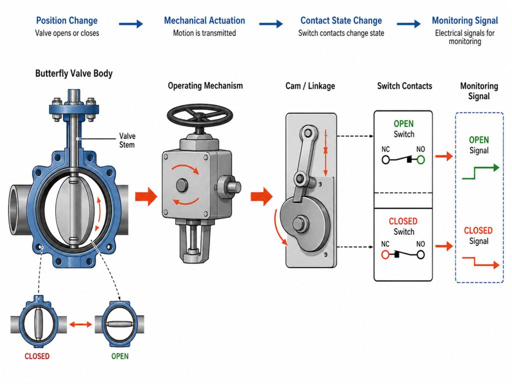
The valve and switch work correctly only when disc travel, operator travel, contact change, and panel interpretation agree. The butterfly disc rotates inside the pipe, the stem transmits that movement to the gear operator, and a cam or linkage actuates the switch contacts.
When the valve leaves the normal position, the contact state changes. The fire alarm input circuit or addressable monitor module interprets that change and identifies a supervisory condition at the panel. When the valve returns fully open, the mechanical mechanism and electrical circuit must both return to their documented normal state.
This chain creates two important failure modes. A late or misadjusted switch may let the valve move while the panel still shows normal, creating a false-normal condition. A wiring, adjustment, or reset problem may keep the panel in supervisory even when the valve is fully open. Selection and handover must test both directions rather than only confirming that a switch can change state on a workbench.
Tamper, Waterflow, and Position Feedback Are Different
These signals answer different operational questions and should not be treated as substitutes. The table separates their functions and limits.
| Signal | What changes it | Usual meaning | What it cannot prove |
|---|---|---|---|
| Tamper or valve supervisory | The valve leaves its required supervised position | The water-supply control valve is off-normal | Water is flowing, a fire exists, or the exact disc angle |
| Waterflow | Water moves through the sprinkler system at the device’s operating threshold | A sprinkler discharge or system test may be occurring | Every upstream control valve is fully open |
| Actuator limit or position feedback | An actuator cam, limit switch, or transmitter reaches a set position | The control system receives a commanded or measured valve status | Fire-service listing or acceptance of the supervised assembly |
The practical conclusion is simple: a tamper signal tells you to investigate valve readiness, while waterflow addresses sprinkler-system activation. As a current code example, the 2025 California Building Code requires water-supply control valves on applicable automatic sprinkler systems to be electrically supervised by a listed fire alarm control unit, and it requires alarm, supervisory, and trouble signals to be distinct. Your project must follow its adopted code edition and authority having jurisdiction rather than treating this example as a universal rule.
Integrated and External Switches Need Different Checks
An integrated and an external switch can perform the same supervisory task, but their mechanical compatibility and approval paths are different. Decide which arrangement the project accepts before ordering the valve or modifying an operator.
Factory-integrated switch package
A factory-integrated switch is built into or matched with the valve’s gear operator. This can reduce field alignment work because the cam, travel, housing, and contact arrangement are designed as one package. You still need the exact assembly model, listing or approval evidence, contact diagram, electrical rating, enclosure suitability, and documented actuation/reset behavior.
Do not assume that “integrated” means universally compatible with every panel. The panel input type, monitor module, end-of-line arrangement, normal contact state, and point description remain system-design decisions.
External supervisory switch
An external switch is a separate device mounted to a compatible valve or gear housing and engaged by the operator mechanism. For example, one published external control-valve supervisory switch uses two SPDT contacts and a 1/2-inch NPT mounting connection. Those details prove the boundary of that model only; they are not universal specifications for all switches or valves.
For a retrofit, obtain written confirmation that the switch is approved for the valve and operator, then follow the device manufacturer’s mounting and adjustment instructions. Do not improvise a bracket, drill a housing, or assume that any contact change is acceptable. A retrofit must change state at the required valve travel, remain accessible for service, preserve the enclosure rating, and stay within the accepted assembly configuration.
Specify Four Interfaces, Not One Part Number
A reliable specification aligns four interfaces: the valve, the fire-service acceptance path, the supervisory switch, and the fire alarm system. The table shows what to request and which document should control each decision.
| Interface | Confirm before purchase | Controlling evidence |
|---|---|---|
| Valve and piping | Size, pressure and temperature limits, connection, face-to-face dimensions, body/disc/stem/seat materials, operator clearance, normal duty | Valve data sheet and approved drawing |
| Fire-service acceptance | Required listing or approval, exact valve-and-switch model scope, adopted code edition, AHJ requirements | Certification record, project specification, and approved submittal |
| Switch and enclosure | Integrated or external arrangement, contact form and rating, documented normal state, actuation/reset point, conduit entry, environmental rating | Switch data sheet, wiring diagram, and installation instructions |
| Alarm-system interface | Conventional or addressable input, monitor module, end-of-line device, circuit supervision, point label, cause-and-effect, reset behavior | Fire alarm control unit manual and approved electrical drawings |
Pressure rating alone does not establish fire-service suitability. UL Solutions treats butterfly valves as a specific category within its fire-suppression valve testing and certification, so a general-purpose valve data sheet cannot replace certification for the intended fire-protection use.
Body style must also match the piping. Grooved, wafer, lug, and flanged connections affect installation method, available space, fasteners, and maintenance access; this wafer-versus-lug selection guide covers the mechanical differences in more detail. Never infer dead-end capability, flange compatibility, or disc clearance from nominal size alone.
For industrial valve orders, RUITO’s documented manufacturer scope includes drawings, material certificates, and pressure/leak test records. Those records can validate the mechanical valve portion, but they do not replace the supervisory-device certification, field wiring records, or fire alarm control unit programming evidence required for the complete system.
Prove the Signal Chain Before Handover
Handover is complete only when the physical valve, switch contacts, field circuit, panel indication, and point label respond correctly as one chain. Perform the test under the approved impairment procedure and with the responsible sprinkler and fire alarm personnel present.
Use the manufacturer’s instructions and the project test plan to define allowable valve movement and expected signal behavior. Do not copy a generic contact choice or resistor value: those details belong to the exact switch diagram and control-panel manual.
This result table helps the commissioning team interpret what it observes.
| Test state | Mechanical observation | Panel result | Interpretation and next action |
|---|---|---|---|
| Valve fully open | Indicator and open stop agree | Correct point is normal | Record the baseline; this alone does not prove off-normal detection |
| Valve moved off normal as instructed | Disc/operator movement is confirmed | Correct point enters supervisory | Signal chain operates as intended; record the actuation and point identity |
| Valve moved off normal | Switch or panel remains normal | False-normal condition | Stop acceptance; check cam/linkage, contact selection, wiring, module, and programming |
| Valve returned fully open | Indicator and open stop agree | Point remains supervisory or trouble | Resolve adjustment, circuit, labeling, or reset behavior before handover |
The final record should identify the valve tag, exact valve and switch models, panel zone or address, tested normal/off-normal states, and any required reset. A more detailed set of installation, wiring, and testing checks can support the project procedure, but the approved device instructions and local acceptance criteria remain controlling.
Build the Specification Around Readiness
A butterfly valve tamper switch is effective only when the valve is mechanically suitable, the supervisory device is accepted for that assembly, and the control panel interprets its contacts correctly. Treating the switch as a minor add-on leaves gaps in listing, environmental protection, wiring, labeling, and commissioning.
Send the pipe size, connection, pressure, materials, required fire-service approvals, indoor or outdoor location, switch arrangement, control-panel interface, project standard, and documentation requirements with your RFQ. RUITO can review the manufacturer-side valve scope and identify which drawings and test records can be supplied; contact our engineering team to start a specification review.
FAQ
Does the switch show the exact butterfly valve opening percentage?
Usually not. A typical tamper switch provides a discrete normal/off-normal contact state; continuous position indication requires a compatible transmitter or actuator-feedback device designed for that purpose.
Can I add a tamper switch to an existing butterfly valve?
Only when the switch, mounting method, valve operator, and approval scope are compatible. Confirm the exact model combination and installation instructions before modifying the gear housing or ordering a retrofit kit.
Why do butterfly valves with tamper switches vary so much in price?
Price changes with valve size, pressure rating, connection type, body and seat materials, required listings, integrated versus external switch design, enclosure rating, documentation, and order quantity. Compare quotations only after those requirements are aligned.