
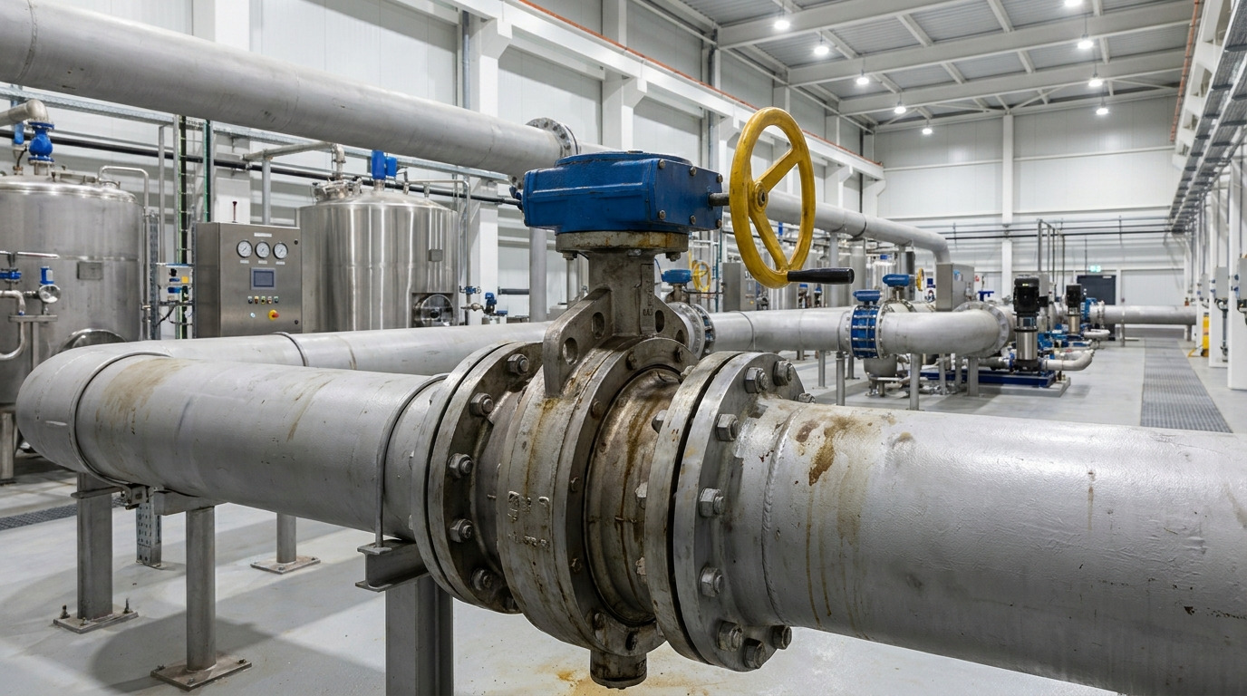
Butterfly valve design uses a rotating disc, shaft, seat, and body to isolate or regulate flow within a pipeline. Yet selecting a valve by pipe diameter alone can lead to unstable control, premature seat wear, or an actuator that cannot close under pressure. A sound butterfly valve design matches geometry, materials, connections, and actuation with real operating conditions.
You may be specifying a cooling-water line where installation space is tight and shutdown windows are short. A poorly matched valve could leak after several cycles, increase pressure loss, or delay commissioning. This guide shows how each design choice solves those risks and helps you prepare a dependable B2B valve specification.
How Does Butterfly Valve Design Control Flow?
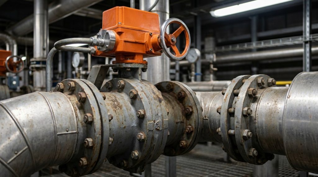
Butterfly valve design controls flow by rotating a circular disc through approximately 90 degrees. A shaft transfers operator or actuator torque to that disc, while a seat provides shutoff at its closed position. You can use this compact arrangement for isolation, throttling, or both when operating limits support each duty.
What Happens as the Disc Rotates?
A fully closed disc blocks fluid through contact with its seat. Rotation increases available flow area, although flow does not rise in direct proportion to disc angle. Disc profile, shaft position, and downstream pressure recovery shape actual capacity.
Which Components Affect Performance?
Here’s the practical point: every component influences leakage, torque, or service life.
- Body geometry sets connection strength and face-to-face length.
- Disc shape affects resistance and flow capacity.
- Shaft alignment changes torque transmission.
- Seat construction governs shutoff and media compatibility.
- Bearings support smooth repeated movement.
| Component | Main duty | Specification check |
|---|---|---|
| Body | Contains pressure | Material and rating |
| Disc | Controls flow | Profile and corrosion resistance |
| Shaft | Transfers torque | Strength and alignment |
| Seat | Seals the port | Fluid and temperature limits |
This comparison shows why a complete valve drawing carries more value than a nominal size alone.
Key Takeaway: You can prevent many sizing and reliability problems by checking every pressure-containing and moving component as one assembly.
Why Choose a Resilient-Seated Concentric Valve?
A resilient-seated concentric valve suits moderate-pressure water, HVAC, and general utility service because its butterfly valve design places the shaft through the disc centerline. Continuous contact between disc and elastomer seat provides tight shutoff. That contact also creates friction during movement, making material selection and cycle frequency relevant.
Where Does a Concentric Arrangement Work Well?
Concentric valves offer low weight, compact installation, and economical replacement. They commonly handle clean water, air, and compatible low-temperature process fluids. You should verify velocity, differential pressure, and expected operating cycles before using one for continuous modulation.
Which Resilient Seat Fits Your Medium?
But here’s the catch: no elastomer suits every fluid.
- EPDM commonly serves water and many HVAC duties.
- NBR often suits oils and hydrocarbon-compatible service.
- FKM supports selected chemicals and higher temperatures.
- Natural rubber may suit abrasive water-based media.
| Seat | Typical strength | Main caution |
|---|---|---|
| EPDM | Water and weather resistance | Petroleum exposure |
| NBR | Oil resistance | Ozone and hot-water limits |
| FKM | Heat and chemical resistance | Higher purchase cost |
| Natural rubber | Abrasion resistance | Oil incompatibility |
The pattern confirms that fluid chemistry matters more than a familiar material name.
Key Takeaway: You gain reliable concentric-valve service when seat chemistry, temperature, pressure, and cycle rate are reviewed together.
How Do Polymer-Lined Valves Handle Corrosive Media?
Polymer-lined valves isolate corrosive fluids through a butterfly valve design that places a resistant liner between process media and vulnerable body surfaces. PTFE or PFA linings can support chemical-processing duties where ordinary elastomers swell, crack, or lose sealing force. Disc coating and shaft protection still require equal attention.
How Do PTFE and PFA Liners Differ?
PTFE offers broad chemical resistance and a low-friction surface. PFA can provide similar resistance with melt-process characteristics that support dense, flexible linings. Your choice should reflect permeation risk, thermal cycling, vacuum conditions, and manufacturing quality.
What Should You Check Before Selection?
This is where details matter: a chemical name alone rarely defines service.
- Record concentration and possible contaminants.
- Confirm minimum and maximum process temperatures.
- Check vacuum and pressure-cycle conditions.
- Review liner thickness and spark-testing records.
- Match disc coating with liner performance.
| Review item | Risk if overlooked | Required evidence |
|---|---|---|
| Concentration | Chemical attack | Process data |
| Temperature | Softening or distortion | Rating curve |
| Vacuum | Liner collapse | Vacuum qualification |
| Permeation | Body corrosion | Material compatibility |
This table shows why a complete operating envelope produces a safer lining decision.
Key Takeaway: You reduce corrosion risk by treating liner, disc, shaft, and process data as one material system.
What Makes a High-Performance Valve Different?
A high-performance valve uses a double-offset butterfly valve design to reduce rubbing between disc and seat. One offset moves the shaft away from the sealing plane, while another shifts it from pipe centerline. This geometry lifts the disc from its seat early during opening and lowers wear during frequent cycling.
Why Do Two Offsets Reduce Seat Wear?
Camming action limits sliding contact across much of disc travel. Less rubbing can lower operating torque and preserve seat condition under higher pressure or temperature than many concentric valves accept. Actual capability still depends on seat construction and pressure direction.
Which Seats Support Demanding Service?
What does that mean for you? seat architecture defines the practical operating window.
- Reinforced PTFE supports many process services.
- Energized seats maintain contact across pressure changes.
- Fire-safe arrangements pair soft sealing with metal backup.
- Metal seats support hotter or dirtier duties.
| Seat style | Main benefit | Common duty |
|---|---|---|
| Soft polymer | Tight shutoff | Clean process fluids |
| Energized polymer | Stable contact | Pressure variation |
| Fire-safe | Backup sealing | Flammable media |
| Metal | Heat and wear resistance | Hot or dirty service |
The selection trend links harder duties with stronger seat support and lower dependence on soft materials.
Key Takeaway: You can extend cycle life by matching double-offset geometry with pressure direction, seat force, and actuator torque.
Why Use a Triple-Offset Butterfly Valve?
A triple-offset valve applies butterfly valve design with two shaft offsets plus an inclined conical sealing geometry. Disc and seat make contact near the end of closing rather than rubbing through most travel. Applied torque then loads metal sealing surfaces for shutoff.
How Does the Third Offset Change Sealing?
The conical angle removes sliding interference between sealing surfaces during opening. That movement supports high-temperature, high-cycle, or demanding isolation duties. Replaceable seal rings can also simplify planned maintenance when their construction allows field service.
Where Does Triple-Offset Geometry Add Value?
Now consider the operating extremes: metal sealing broadens application choices.
- Steam distribution and hot process lines
- Hydrocarbon transfer and tank terminals
- Cryogenic gas and liquid systems
- Turbine bypass or hot-air service
- Duties requiring fire-resistant construction
| Service condition | Design response | Check before ordering |
|---|---|---|
| High temperature | Metal sealing | Expansion and material limits |
| Cryogenic duty | Extended bonnet | Low-temperature toughness |
| Frequent cycling | Low-rub movement | Dynamic torque data |
| Fire exposure | Metal seal path | Test qualification |
This summary connects severe conditions with features that must appear in project documentation.
Key Takeaway: You gain the most from triple-offset geometry when demanding temperature, cycling, or fire conditions justify its added complexity.
Which Butterfly Valve End Connection Fits Your Pipeline?
The right connection fits installation, maintenance, and isolation needs through a butterfly valve design compatible with both mating flanges and service pressure. Wafer, lug, double-flanged, and welded bodies use different bolting or joining methods. Their nominal sizes do not make them interchangeable.
When Should You Use Wafer or Lug Bodies?
Wafer bodies fit between two flanges and offer a short, light assembly. Lug bodies use threaded body lugs and may support removal of one downstream pipe section when rated for dead-end duty. You should confirm any pressure derating for that arrangement.
What About Flanged and Welded Ends?
Here’s what procurement teams often miss: connection style changes installation scope.
- Double-flanged bodies support larger sizes and rigid piping.
- Welded ends remove a bolted external leak path.
- Wafer bodies reduce weight and initial cost.
- Lug bodies give greater maintenance flexibility.
| Connection | Main advantage | Main limitation |
|---|---|---|
| Wafer | Compact and economical | Limited dead-end use |
| Lug | Service flexibility | Added weight |
| Double-flanged | Structural support | Larger footprint |
| Welded | Permanent joint | Difficult removal |
The comparison points toward maintenance access as a major selection factor.
Key Takeaway: You avoid site rework by confirming flange standard, drilling, face-to-face length, bolting, and dead-end rating before purchase.
How Should You Select Butterfly Valve Actuation?
Actuation should supply enough torque and control for every operating condition that the butterfly valve design may encounter. Manual levers and gears suit local operation, while pneumatic, electric, or hydraulic actuators support remote control. Differential pressure, seat friction, frequency, and fail position affect required output.
When Is Manual Operation Practical?
A lever works well on smaller valves with modest torque and accessible installation. Gear operators reduce hand force on larger sizes or higher-pressure duties. Neither choice suits rapid emergency action when an operator cannot reach the valve immediately.
Which Powered Actuator Matches Your Process?
Ready for the deciding factors? power source and failure response narrow your options.
- Pneumatic units offer fast action and spring-return choices.
- Electric units suit sites with stable electrical power.
- Hydraulic units provide high torque for heavy-duty valves.
- Positioners support modulating control and feedback.
| Actuator | Strong point | Site requirement |
|---|---|---|
| Manual | Simple local control | Physical access |
| Pneumatic | Fast fail-safe action | Clean compressed air |
| Electric | Easy remote integration | Reliable power |
| Hydraulic | High output torque | Hydraulic power unit |
This comparison shows that actuator choice begins with site utilities and safety response rather than purchase price.
Key Takeaway: You protect valve movement by calculating torque at maximum differential pressure and applying a suitable service margin.
Which Standards Govern Butterfly Valve Design?
Applicable standards define dimensions, ratings, tests, and interfaces for a butterfly valve design. API, ASME, EN, ISO, MSS, and AWWA documents may each govern different parts of one project. A specification should state editions and acceptance criteria instead of listing acronyms without context.
What Does a Design Standard Cover?
A design document may address body construction, shaft retention, pressure capability, and valve categories. Separate standards can govern face-to-face dimensions, flange drilling, actuator mounting, pressure testing, or leakage. Project location and end-user rules determine which combination applies.
What Documentation Should a Supplier Provide?
Here’s the verification step: compliance needs records.
- Approved drawings and bills of materials
- Material certificates with heat traceability
- Shell and seat pressure-test reports
- Coating or lining inspection results
- Torque data and actuator calculations
- Nameplate and packing-list checks
| Document | What it verifies | Review stage |
|---|---|---|
| Drawing | Dimensions and interfaces | Before production |
| Material certificate | Grade and traceability | Incoming inspection |
| Test report | Pressure integrity | Before shipment |
| Torque sheet | Actuator suitability | Design approval |
This document trail lets engineering and quality teams resolve mismatches before valves reach site.
Key Takeaway: You make standards useful by connecting every cited requirement with a drawing, inspection record, or acceptance test.
Where Do Butterfly Valves Perform Best?
Butterfly valves perform best where compact dimensions, quick quarter-turn action, and moderate pressure loss support system goals. Their butterfly valve design works across water, HVAC, chemical, marine, power, and utility lines when materials match each medium. Severe slurry or extreme pressure-drop duties may need another valve style.
Which Duties Favor Butterfly Valves?
Isolation duties benefit from fast closing and a short face-to-face dimension. Throttling duties can work well when normal flow remains within a stable middle travel range. Large-diameter water systems often benefit from lower mass compared with many gate or ball arrangements.
When Should You Consider Another Valve?
The boundary matters: versatility does not mean universal suitability.
- Consider a knife gate for heavy fibrous slurry.
- Consider a globe valve for precise low-flow modulation.
- Consider a full-port ball valve where an unobstructed bore matters.
- Review specialized trim for severe cavitation or noise.
| Operating need | Likely choice | Main reason |
|---|---|---|
| Large water line | Butterfly valve | Compact construction |
| Fine low-flow control | Globe valve | Greater control resolution |
| Heavy slurry | Knife gate | Open flow path |
| Pigging service | Full-port ball valve | Clear bore |
The comparison helps you separate genuine application fit from a simple preference for one valve family.
Key Takeaway: You make a stronger valve choice by defining control accuracy, solids content, pressure loss, and maintenance access early.
How Do You Size a Butterfly Valve Correctly?
Correct sizing matches required flow and available pressure drop with a butterfly valve design that operates within a stable disc-angle range. Matching pipe diameter alone can oversize a control valve. That error may cause hunting, noise, rapid seat wear, or weak response near full opening.
How Do Cv and Disc Angle Work Together?
Cv describes valve flow capacity under defined conditions. For throttling service, you need Cv data at several disc angles rather than only a full-open value. Compare minimum, normal, and maximum flow against available differential pressure and fluid properties.
What Should Your Sizing Worksheet Include?
Here’s the sizing sequence: build decisions from process data.
- Record fluid composition, density, and temperature.
- Define minimum, normal, and maximum flow.
- Calculate available pressure drop at each condition.
- Check cavitation, velocity, noise, and flashing risk.
- Verify torque across full travel.
- Confirm seat leakage and fail position.
| Sizing input | Engineering purpose | Common error |
|---|---|---|
| Flow range | Sets required capacity | Using maximum flow only |
| Pressure drop | Determines Cv demand | Using pump pressure |
| Fluid properties | Corrects calculation | Assuming water |
| Torque data | Sizes actuator | Ignoring seat friction |
This worksheet exposes missing inputs before they become purchase-order assumptions.
Key Takeaway: You gain stable control by sizing around real operating points and then verifying valve curves, pressure limits, and torque data.
What Should You Take Forward?
Butterfly valves combine compact construction with fast operation and broad material choices, but dependable results come from disciplined specification. This article addressed geometry, seats, linings, offsets, connections, actuation, standards, applications, and sizing so you can identify risks before procurement or installation.
For application review, material guidance, drawings, or actuator support, contact us today with your fluid data and operating conditions. We help you turn process requirements into traceable valve selections because reliable flow control should begin with engineering evidence, not assumptions.
FAQ
Can I use a butterfly valve for throttling?
Yes, in suitable service. Check its Cv curve, available pressure drop, usable disc-angle range, actuator resolution, and cavitation risk before specifying continuous control.
What’s the best butterfly valve for water service?
A resilient-seated concentric model is often a practical choice. Water chemistry, temperature, pressure, velocity, certification, and expected cycle rate should still guide seat and body materials.
How do I know if I need a double-offset valve?
Choose one when pressure, temperature, or cycle frequency exceeds the comfortable range of a concentric model. Reduced seat rubbing can support lower wear and more consistent torque.
Can I install a wafer valve for dead-end service?
Usually not without explicit approval. Use a lug or flanged valve carrying a documented dead-end pressure rating for your intended flow direction and operating condition.
What’s the best information to send a valve supplier?
Send fluid composition, size, flow range, pressure, temperature, connection standard, leakage class, actuation method, fail position, and required certificates. Clear data supports faster and more accurate technical review.