
Ball valve disassembly is useful only when the valve can be isolated safely, the likely failure point is repairable, and the parts can be inspected without damaging the sealing surfaces. In industrial piping, the real problem is rarely “how to open the valve” alone; it is how to control stored energy, protect the ball and seats, identify whether the valve is worth rebuilding, and confirm that the reassembled valve can return to service.
This guide is for maintenance planners, plant technicians, piping engineers, and purchasing teams who need a practical way to approach disassembly before replacing or reordering industrial ball valves. It covers safety preparation, disassembly order, inspection points, testing logic, and the point where replacement becomes more sensible than repair.
When Ball Valve Disassembly Is the Right Move
Disassembly is the right move when the valve has a diagnosable mechanical problem and the site can remove pressure, media, and actuator energy under a controlled procedure. It is not a shortcut for forcing a stuck valve, tightening random fasteners, or reusing worn seats in a critical line.
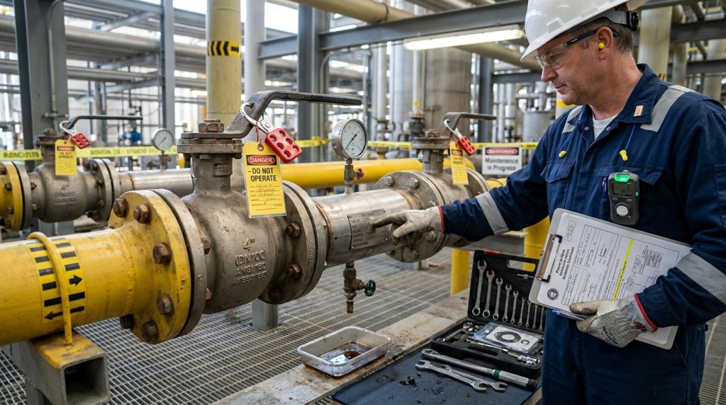
A valve may justify opening when leakage continues after correct external adjustment, when the stem packing area needs inspection, when the ball will not rotate smoothly after external causes are ruled out, or when contamination may have damaged the seat. If the issue is only a handle, actuator setting, signal fault, or coupling problem, opening the valve body may add risk without solving the root cause.
Before work begins, identify the valve type. A floating ball valve, trunnion-mounted ball valve, three-piece valve, top-entry valve, and fully welded valve do not have the same repair boundary. A three-piece valve may be designed for easier bench service, while a welded body normally pushes the decision toward replacement or factory-level evaluation.
For electric or automated valves, separate the valve problem from the actuator problem. If a valve is stuck because torque demand has increased, the valve internals may need inspection. If the actuator, limit switch, coupling, or mounting bracket is the issue, opening the pressure boundary is usually the wrong first step. A structured diagnosis of a ball valve stuck on an automated actuator helps keep those two failure paths separate.
Safety Checks Before Opening a Ball Valve
The first task is to make the valve safe, not to remove bolts. Any ball valve can trap pressure, residual media, or actuator energy, and the hazard increases with hot fluids, corrosive media, gas service, and remote operation.
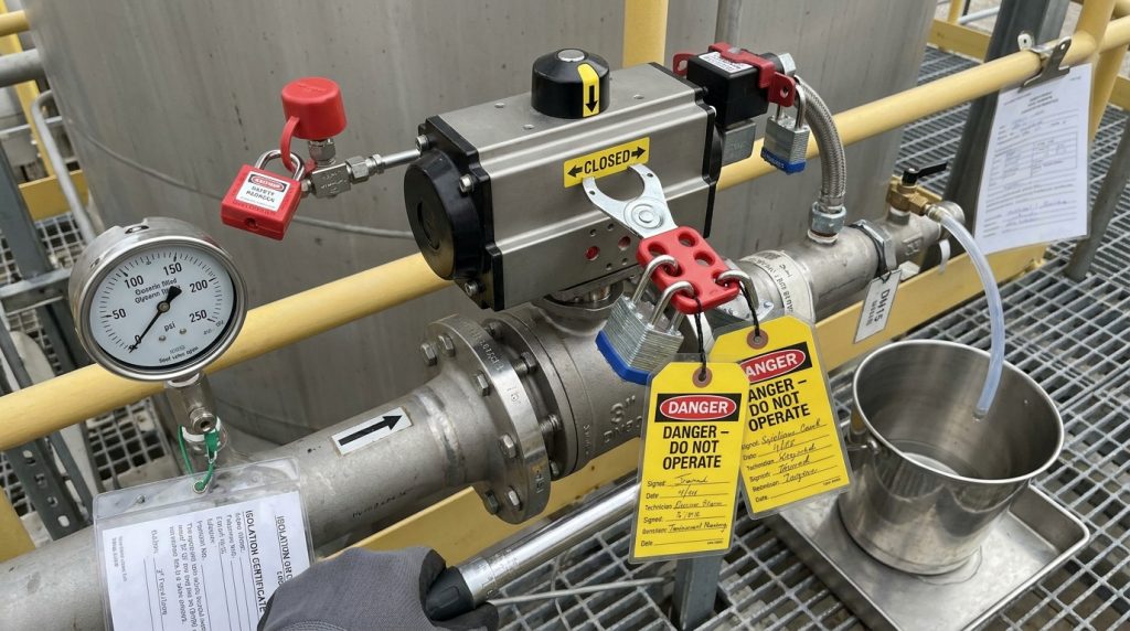
For U.S. workplaces, OSHA’s lockout/tagout rule states that after energy isolating devices are locked or tagged, potentially hazardous stored or residual energy must be made safe, and isolation must be verified before servicing begins under 29 CFR 1910.147. Even outside the U.S., the same principle is useful: isolate, depressurize, drain, verify, and prevent unexpected operation.
Do not assume a ball valve is empty because the pipeline pressure gauge reads zero. The cavity between the seats can retain media, especially in double-blocking arrangements, viscous fluids, or dirty service. Use the plant’s approved venting and draining method, and treat trapped fluid as hazardous until its identity and temperature are confirmed.
Confirm Isolation and Media Condition
Check upstream and downstream isolation, pressure gauges, drains, vents, and any bypasses. If the line carries steam, hydrocarbons, chemicals, compressed air, or slurry, confirm the procedure for cooling, purging, flushing, and disposal before the body is opened.
If the valve has failed in the partly open position, do not force it just to reach an ideal disassembly position. Excess torque can twist the stem, score the ball, or crack brittle deposits. When resistance is the main symptom, diagnose a ball valve that will not turn before adding leverage.
Prepare Tools and Replacement Parts
Prepare non-sparking or corrosion-resistant tools where the site procedure requires them, soft lifting support for heavy valves, clean trays for small components, and material-compatible cleaning supplies. Replacement seats, body seals, stem packing, thrust washers, O-rings, and gland parts should match the valve design, pressure class, temperature range, and media compatibility.
Avoid generic seal kits unless the valve manufacturer or project specification confirms compatibility. A seat that fits dimensionally can still fail if the material is unsuitable for temperature, chemical exposure, abrasion, or required shutoff performance.
Step by Step Ball Valve Disassembly Process
A controlled ball valve disassembly should move from external components to pressure-retaining joints, then to the stem, seats, and ball only after orientation and component order are documented. The goal is to preserve evidence of failure while preventing secondary damage during teardown.
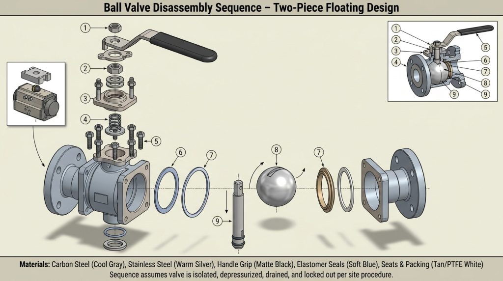
Start by photographing the installed valve, flow direction, nameplate, actuator position, wiring labels, and flange orientation. Mark the open and closed position if the indication may be disturbed during handling. For electric valves, disconnect and label power and control wiring only under the site’s electrical procedure.
Remove the Operator or Actuator First
Remove the handle, gearbox, pneumatic actuator, or electric actuator according to its mounting arrangement. For actuated packages, record bracket position, coupling orientation, limit switch position, and any mechanical stops before separation. ISO 22153:2020 covers general requirements for electric valve actuators, including design, enclosure, corrosion protection, and conformity assessment for electric actuators used on on-off and control valves, while excluding some actuator types such as solenoid and electro-hydraulic units under its stated scope.
Once the actuator is removed, check whether the stem can be turned by hand with appropriate tools and within safe limits. If the valve still binds, the problem is more likely internal: seat swelling, corrosion, solids, galling, thermal distortion, or ball damage.
Open the Body Without Damaging Sealing Surfaces
For split-body or three-piece valves, loosen body bolts in a controlled pattern after the valve is supported. Do not pry against machined sealing faces. If the joint does not separate easily, look for hidden fasteners, corrosion, seal adhesion, or trapped pressure before applying force.
Remove the body seal or gasket and keep it for inspection. Its condition can reveal compression set, chemical attack, extrusion, incorrect material, or uneven bolt loading. Discard seals that are intended for one-time use or that show deformation, cuts, swelling, or hardening.
Remove Ball, Seats, Stem, and Packing
Rotate the ball only as needed to remove it safely, and lift it without scratching the polished sealing surface. Remove seats and support rings carefully; non-metallic seats can be damaged by picks, screwdrivers, or sharp tools.
Push or pull the stem only in the direction intended by the valve design. Many industrial ball valves use anti-blowout stems, meaning the stem is retained from inside the body and cannot simply be pulled outward. Keep packing rings, gland followers, thrust washers, and anti-static parts in order so wear patterns can be understood during inspection.
What to Inspect After the Valve Is Open
Inspection should decide whether the valve can be rebuilt, should be replaced, or needs a different specification for the next order. Cleaning is important, but do not remove all evidence before checking where leakage, torque increase, corrosion, or seat damage started.
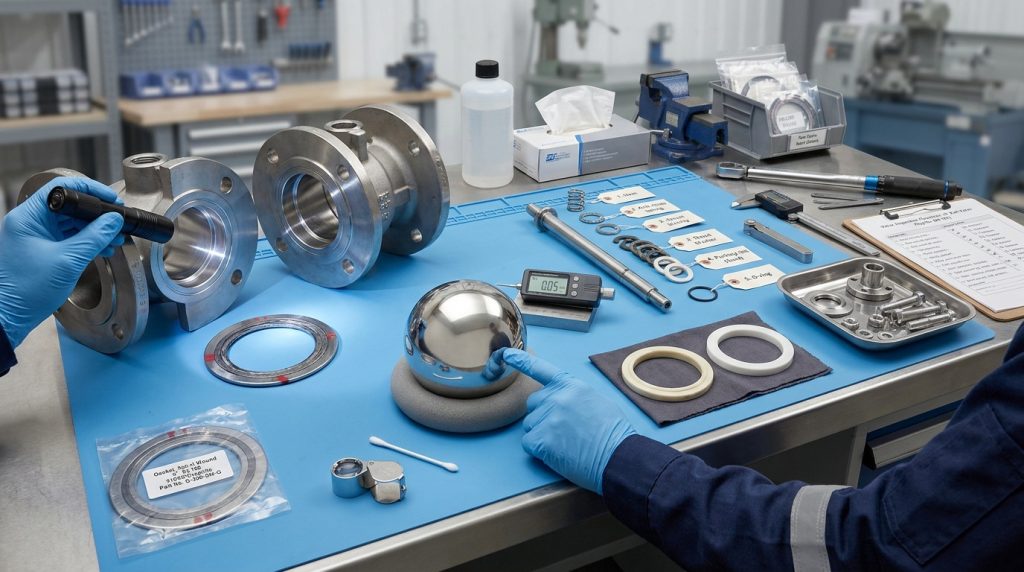
Look first at the ball surface. Scratches across the sealing path, embedded solids, pitting, coating loss, or edge damage can prevent reliable shutoff even with new seats. Then inspect seats for compression set, swelling, erosion, tearing, heat damage, or chemical softening.
Stem packing tells a different story. Leakage at the stem may come from packing relaxation, stem scratches, gland misalignment, thermal cycling, or over-tightening. If the stem is scored, replacing packing alone may only delay another leak.
The following table helps connect inspection findings with the standards or specification points that should be checked before reuse or replacement.
| Inspection Area | What to Verify | Why It Matters |
|---|---|---|
| Valve size, class, and end connection | ISO 17292:2015 covers metal ball valves for petroleum, petrochemical, natural gas, and related industrial applications, including DN 8 to DN 600 and pressure designations such as Class 150, 300, 600, 800 and PN 16 to PN 100 within its stated scope on the ISO 17292:2015 page. | The repair kit, gasket, seat design, and replacement valve must match the actual valve specification, not only the pipe size. |
| Pressure boundary and closure test | ISO 5208:2015 is used with relevant product standards to verify pressure-boundary integrity, closure tightness, and structural adequacy of metallic industrial valves under its pressure-testing scope. | A rebuilt valve should not return to service just because it “looks clean”; it needs an applicable test basis. |
| Body, flange, thread, or weld-end suitability | ASME B16.34 covers pressure-temperature ratings, dimensions, tolerances, materials, nondestructive examination, testing, and marking for new flanged, threaded, and welding-end valves under its published scope. | Body or end-connection damage may make replacement safer than rebuilding, especially where pressure-temperature ratings are critical. |
| Electric actuator package | ISO 22153:2020 addresses electric actuator requirements for on-off and control valves, including enclosure and corrosion protection considerations. | If actuator ingress, corrosion, or limit setting caused the problem, valve-body repair alone may not prevent repeat failure. |
Use the table as a verification guide, not as a universal acceptance rule. The controlling project standard, purchaser specification, local regulation, and manufacturer’s maintenance instructions should decide the final inspection and test requirements.
Reassembly, Testing, and Replacement Decisions
Reassembly should restore the valve’s pressure boundary, sealing geometry, stem packing load, and operating torque without improvising parts. If those conditions cannot be met, replacement is usually the more responsible decision.
Install new seals in clean grooves and confirm orientation before tightening. Lubricants, if used, must be compatible with the seat, seal material, valve material, and media. In oxygen, potable water, high-temperature, chemical, or gas service, lubricant selection is not a casual maintenance choice.
Tighten bolts according to the valve manufacturer’s procedure or the approved plant specification. Uneven tightening can distort the body joint, change seat loading, or create leakage that looks like a defective gasket but actually comes from assembly error.
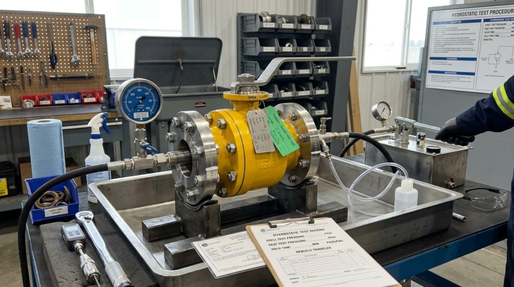
Test Before Returning to Service
After reassembly, cycle the valve through its normal travel and check for smooth movement, correct position indication, and stable torque. For actuated valves, verify open and closed limits, manual override condition, coupling alignment, and fail position if applicable.
Pressure and seat testing should follow the applicable project standard. For metallic industrial valves, ISO 5208:2015 is one recognized framework for checking pressure-boundary integrity and closure tightness, but the correct test method depends on the valve product standard and the purchaser’s specification.
Know When Replacement Is Better
Replacement may be the better decision when the ball is deeply scored, the body sealing face is corroded, the stem is bent or worn, the valve lacks traceable parts, or the old design is mismatched to the service. Repeated seat failure often points to abrasive media, excessive temperature, poor material compatibility, pressure drop damage, or actuator torque mismatch rather than a simple maintenance issue.
From a manufacturer’s perspective, repeat failures should lead back to specification review. Seat material, bore type, floating versus trunnion design, end connection, actuator sizing, and quality controls in the ball valve manufacturing process can affect whether the next valve survives the same service conditions.
A practical repair decision path is simple: confirm safety, identify the failure mode, inspect the pressure parts, verify part compatibility, test the rebuilt valve, and only then approve reuse. If any step is uncertain, a controlled replacement review is better than putting an unknown valve back into a critical line.
Conclusion
Ball valve disassembly is not just a maintenance step; it is a controlled decision process that connects safety, valve construction, sealing materials, actuator behavior, inspection evidence, and post-reassembly testing. Done carefully, it can reveal whether a valve needs a seal kit, a corrected actuator setup, a different material choice, or full replacement.
RUITO’s position is that durable valve supply starts with clear engineering communication before the next order is built, especially when maintenance findings show seat damage, stem leakage, torque increase, or repeated shutoff problems. For a project review, you can share your valve specifications and operating conditions so the discussion can focus on valve type, material, pressure rating, connection, actuator configuration, and replacement suitability.
FAQ
Can every ball valve be disassembled for repair?
No, not every ball valve is practical or intended to be disassembled. Three-piece and some split-body designs are generally more serviceable, while welded-body or severely corroded valves often push the decision toward replacement.
Should the valve be open or closed before disassembly?
It depends on the valve design and the maintenance procedure. Many technicians position the ball to reduce trapped media and allow safe removal, but the priority is verified isolation, depressurization, draining, and protection of the sealing surfaces.
What parts are usually replaced during ball valve reassembly?
Seats, body seals, O-rings, stem packing, and some thrust or gland components are commonly replaced when the valve is opened. Reusing old soft seals can create repeat leakage, especially after compression set, chemical swelling, or heat exposure.
How do I know whether the actuator or valve body caused the problem?
Start by separating signal, power, limit switch, coupling, bracket, and torque issues from internal valve resistance. If the stem remains difficult to move after the actuator is removed and the valve is safely isolated, internal seat, ball, corrosion, or solids damage becomes more likely.
What information helps a supplier review a replacement valve?
The most useful information includes valve type, size, pressure class or PN rating, end connection, body and seat material, medium, temperature, pressure, actuator type, failure symptom, and any applicable project standard. Photos of the nameplate and failed parts can also help avoid mismatched replacements.