
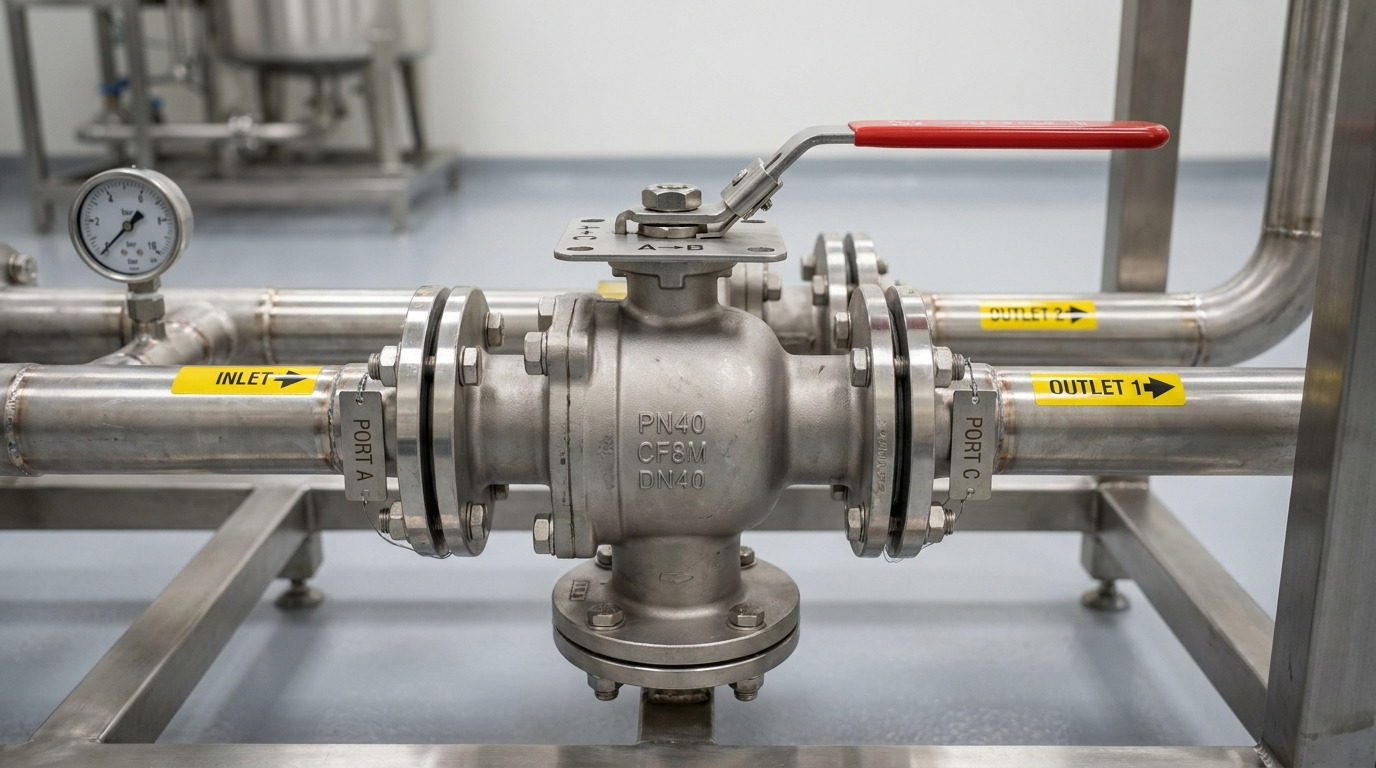
A 3-way ball valve diagram should show which ports are connected, which port is blocked, and how the L-port or T-port ball changes flow as the stem turns. For engineers, buyers, and skid builders, the main value of the diagram is not decoration; it prevents wrong port orientation, wrong actuator logic, and the wrong valve being ordered for mixing or diverting service.
In a real project, the pain usually appears when a simple sketch says “3-way valve” but does not define whether the valve must switch between two outlets, mix two inlets, bypass equipment, or isolate a branch. That is where the diagram needs to work together with the basic ball valve specification, including port type, body material, seat material, end connection, pressure class, and actuation method.
What a 3-Way Ball Valve Diagram Must Show
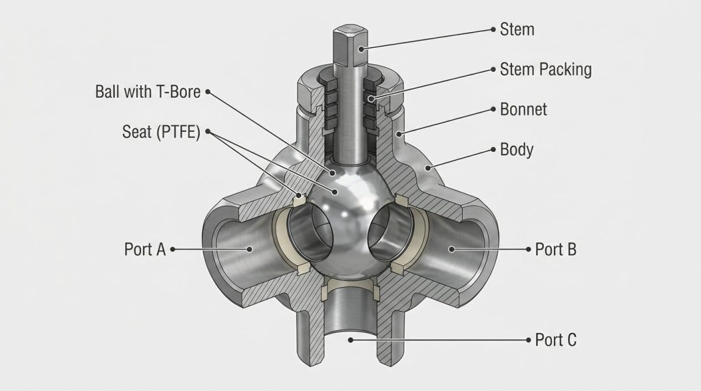
A 3-Way Ball Valve Diagram must identify the port labels, the ball bore shape, the stem position, and the permitted flow directions. Without those four items, the drawing may look understandable but still leave room for a costly routing mistake.
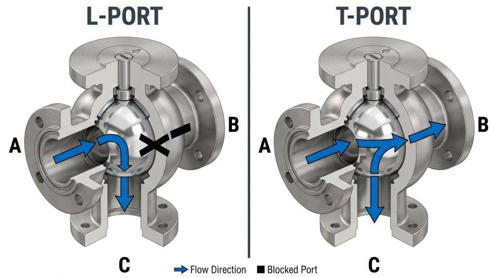
A three-way valve has three external ports, commonly labeled A, B, and C or 1, 2, and 3. The internal ball has either an L-shaped bore or a T-shaped bore. When the stem rotates, the bore aligns with different ports and changes the flow path.
Port Labels and Common Port
The common port is the port that remains central to the operating logic. In many diverting duties, one inlet alternates between two outlets. In mixing duties, two inlets may combine into one outlet, but only if the valve design, pressure balance, and process conditions allow that duty.
Do not assume that the bottom port, side port, or center port is automatically the common port. The supplier’s flow chart and port marking should define it clearly.
Ball Bore Shape and Handle Position
The handle or actuator indicator usually follows the stem position, but it does not fully explain the internal flow path unless the ball pattern is known. An L-port ball connects two adjacent ports, while a T-port ball can connect straight-through flow, side flow, or several ports depending on the stop arrangement.
A useful diagram should show both the external valve body and a simplified internal bore. This helps the reader see why two valves with the same three connections may behave very differently.
L-Port Diagrams Show Switching Between Two Paths
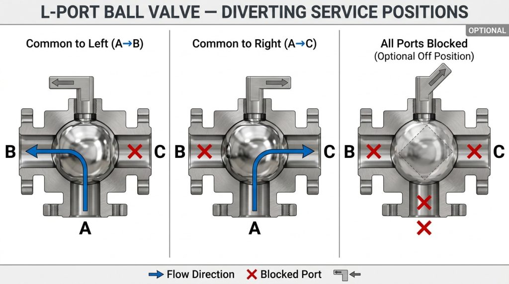
An L-port diagram mainly shows flow switching between two connected ports at a time. It is usually chosen when the system needs to divert flow from one line to another, not when it needs continuous mixing through all three ports.
For example, one common port may connect to branch A in one position and branch B after rotation. Depending on the valve design and stop plate, there may also be a closed position, but that should never be assumed from the words “L-port” alone.
Where L-Port Valves Fit
L-port valves are often used for alternate routing, such as switching between two tanks, two filters, two pumps, or two process lines. The main question is whether the process needs clean selection between paths rather than simultaneous flow.
If the system requires both outlet branches to receive flow at the same time, an L-port pattern is usually the wrong starting point. A T-port design or a different valve arrangement may be more suitable.
What the Diagram Should Clarify
A good L-port diagram should show every allowed position. For each position, mark open ports, blocked ports, and the stem angle. If the valve is automated, the diagram should also show whether the actuator travels only between two positions or includes an intermediate stop.
This matters because a control panel signal such as “open” and “closed” may not describe the real process state. For a three-way valve, “open” must mean a defined flow path, not just stem movement.
T-Port Diagrams Show Mixing, Diverting, or Straight Flow
A T-port diagram is more flexible, but that flexibility also creates more specification risk. A T-port ball can often support straight-through flow, side branch flow, mixing, or splitting, depending on stem rotation and stop design.
The important point is that “T-port” does not automatically mean every position is available or suitable. Some products use 90-degree stops, some use 180-degree operation, and some are configured for selected flow patterns only.
Mixing and Splitting Need Extra Care
When a T-port valve is used for mixing two streams, the process designer should confirm pressure balance, backflow risk, media compatibility, and whether the valve is intended for modulating or only position-based routing. A ball valve can change routing quickly, but it is not automatically a precision control valve.
When a T-port valve is used for splitting flow, the diagram should show whether the inlet can feed both outlet branches at once. The valve may allow the geometry, but the actual split depends on downstream resistance, pressure drop, and system design.
T-Port Does Not Equal Isolation
Some T-port positions may leave two or three ports connected. If tight branch isolation is required, the diagram must show a verified shutoff position or the piping design may need additional isolation valves.
This is especially important when one branch leads to equipment that will be serviced while another branch remains in operation. The flow diagram should be reviewed with the plant’s isolation and safety procedure, not treated as a standalone safety boundary.
How to Read Rotation Positions Without Misrouting Flow
Read rotation positions as process states, not just handle angles. A 90-degree or 180-degree movement only becomes meaningful when it is tied to a specific port-to-port connection.
The same rotating-ball logic behind a standard ball valve working principle still applies: the bore must align with the ports to permit flow. In a three-way design, that alignment changes more than one possible path.
Manual Handles and Position Stops
For manual valves, the handle, stop plate, and port markings should agree with the diagram. If the handle position is changed in the field or the stop plate is reassembled incorrectly after maintenance, the visible handle may no longer match the intended flow path.
This is why the diagram should show the stem position and not only the pipe layout. A line drawing without stem orientation can hide the most important selection detail.
Actuated Valves and Fail Position
For pneumatic or electric actuation, the diagram should state the fail position or de-energized position if the process depends on it. ISO’s current ISO 5211:2026 covers part-turn actuator attachment requirements, including flange and driving component dimensions, so actuator mounting should be treated as a defined interface rather than an afterthought.
The actuator does not decide the flow pattern by itself. The ball port, stem orientation, travel stop, and control signal mapping must all match the process diagram.
What the Diagram Cannot Replace in a Specification
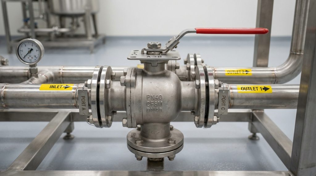
A diagram cannot replace pressure rating, material selection, end connection, leakage test requirements, Cv, or actuator interface details. It only explains routing logic, so the purchase specification must still define the operating envelope.
The table below helps separate what a flow diagram can show from what must be confirmed elsewhere before ordering.
| Specification Item | Why It Matters | Useful External Check |
|---|---|---|
| Valve size and pressure designation | A routing sketch does not prove the valve is suitable for the line class | ISO 17292:2015, confirmed current in 2025, covers metal ball valves from DN 8 to DN 600 and pressure designations including Class 150, 300, 600, 800 and PN 16, 25, 40, 63, 100 |
| Flanged connection details | A three-port body still needs compatible flange dimensions, bolting, and gasket practice | ASME B16.5-2025 covers pipe flanges and flanged fittings from NPS 1/2 through NPS 24, with defined pressure classes and dimensional requirements |
| Actuator mounting | Automation can fail if the mounting interface and torque assumptions are not aligned | ISO 5211:2026 specifies part-turn actuator attachment requirements for industrial valves |
| Flow capacity | A diagram shows direction, not pressure loss or available flow | A valve sizing note defines Cv as US gallons per minute of water at 60°F through a fully open valve with 1 psi pressure differential in that sizing context, as explained in this Cv calculation reference |
The practical takeaway is simple: use the diagram to confirm flow paths, then use standards, datasheets, and project requirements to confirm whether the selected valve can actually operate in the system. When pressure drop matters, the ball valve pressure drop should be checked with the real fluid, flow rate, and port geometry instead of inferred from the drawing.
Application Fit Depends on the Flow Task
The right 3-way valve depends first on the flow task: diverting, mixing, bypassing, or selecting between equipment branches. The same external body can appear similar in a diagram, but the internal bore pattern changes the application fit.
In chemical transfer, water treatment skids, HVAC bypass loops, and utility manifolds, three-way valves are often used to simplify piping. For corrosive or variable media, the flow pattern must be considered together with material and seat selection, especially in chemical-processing valve applications where corrosion, leakage, and compatibility risks can dominate the decision.
Diverting Service
For diverting service, identify the single inlet and two possible outlets. The diagram should show whether one outlet is fully blocked while the other is open, or whether a transition position briefly connects multiple paths.
That transition detail matters for batch systems, metering lines, and systems where cross-contamination is unacceptable.
Mixing Service
For mixing service, identify the two inlets and the common outlet. A T-port pattern may support the geometry, but the process still needs pressure and flow review because the higher-pressure line can influence the lower-pressure branch.
If stable proportioning is needed, a three-way ball valve may not be enough by itself. The design may require control valves, check valves, or instrumentation depending on the process goal.
Bypass and Equipment Selection
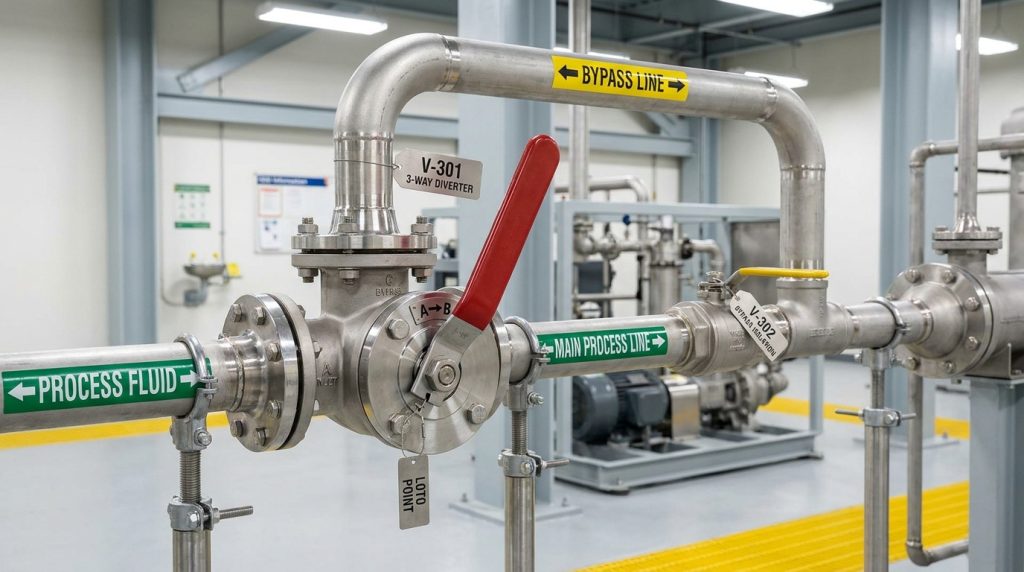
For bypass or duty-standby equipment selection, the diagram should show the normal path and the bypass path clearly. It should also show whether there is any position that isolates equipment for maintenance.
For installed systems, safety rules still apply. OSHA’s lockout/tagout overview explains that hazardous energy control procedures are used to prevent unexpected energy release during servicing and maintenance, so a valve diagram should never replace site isolation procedures.
Common Diagram Mistakes That Cause Selection Risk
Most diagram-related mistakes come from treating a 3-way valve as a simple on-off valve. The risk is not only wrong flow direction; it can also affect cleaning, isolation, pressure loss, actuator logic, and purchasing accuracy.
Common mistakes include:
- Using “L-port” or “T-port” without a full flow position chart
- Failing to identify the common port
- Assuming a center-off position exists when the valve design does not provide one
- Ignoring whether the valve is horizontal or vertical in the actual piping layout
- Selecting an actuator before confirming required travel angle and fail position
- Treating Cv, pressure class, and seat material as secondary details
- Sending an inquiry with a piping sketch but no port numbering
From a valve manufacturer’s perspective, the better inquiry is the one that includes both the diagram and the operating conditions. The ball valve manufacturing process can only produce a suitable valve package when the flow pattern, materials, connections, and testing expectations are defined clearly enough for review.
How to Prepare a Clear Inquiry from a Diagram
A clear inquiry should translate the 3-way ball valve diagram into operating requirements. The goal is to remove ambiguity before quotation, drawing review, or actuator selection.
Include these details when possible:
- Port labels and intended common port
- L-port or T-port pattern
- Required flow position for each handle or actuator state
- Whether shutoff, mixing, diverting, or bypass is required
- Media, concentration if relevant, and cleanliness level
- Working pressure and temperature range
- Connection type and applicable flange, thread, or welding standard
- Valve body, ball, stem, seat, and seal material preferences
- Manual, pneumatic, or electric operation
- Required fail position for automated service
- Any required inspection, testing, marking, or documentation standard
If a diagram is still uncertain, mark the desired process result instead of guessing the internal pattern. A supplier can discuss whether the required function points toward an L-port, T-port, two separate valves, or a custom port arrangement.
Conclusion
A 3-way ball valve diagram is useful when it does more than show three pipe connections. It should explain port labels, internal bore pattern, stem rotation, permitted positions, and the difference between diverting, mixing, bypassing, and isolation.
For RUITO, a useful valve discussion starts with accurate flow logic before moving into materials, pressure class, connection standard, seat design, and actuation. That is a practical brand position: clearer specifications help reduce selection uncertainty before the valve reaches the line.
If you are preparing a three-way valve inquiry, share your port numbering, flow sketch, media, pressure, temperature, connection standard, and actuation plan through RUITO’s project inquiry channel so the routing requirement can be reviewed with the rest of the valve specification.
FAQ
What is the main difference between an L-port and T-port 3-way ball valve?
An L-port valve usually switches flow between two paths, while a T-port valve can support more routing combinations. The exact function still depends on the manufacturer’s flow pattern, stop design, and stem positions.
Can a 3-way ball valve fully shut off all ports?
Some designs can provide an off position, but it should not be assumed. The diagram or datasheet must show a verified closed position if full shutoff is required.
Is a T-port valve better for mixing two fluids?
A T-port valve may be suitable for some mixing layouts, but it is not automatically a precise mixing control device. Pressure balance, flow demand, media compatibility, and control requirements should be reviewed before selection.
Why does the same 3-way valve look different in diagrams?
Different diagrams may use different port labels, viewing angles, handle positions, or vertical versus horizontal orientation. Always compare the diagram with the supplier’s port marking and flow position chart.
What should buyers send with a 3-way valve drawing?
Buyers should send port labels, desired flow positions, media, pressure, temperature, connection type, material preferences, and actuation requirements. That information helps confirm whether the diagram matches a practical valve specification.