
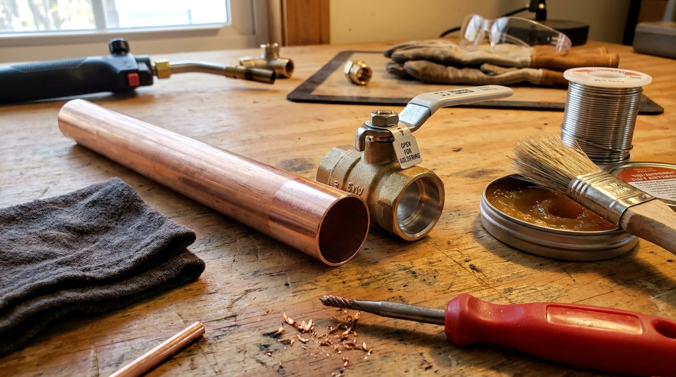
To sweat a ball valve without damaging it, control heat so the solder flows into the copper joint while the valve seats, seals, stem packing, and handle stay outside the main heat path. This guide focuses on the practical installation problem behind the keyword: making a sound soldered connection without overheating the valve body.
In many plumbing, HVAC, process water, and equipment skid assemblies, a sweat-end ball valve is chosen because copper tube is already part of the system. The pain point is that a ball valve is not just a copper fitting; it contains soft sealing parts and a machined ball that can be affected by heat, trapped pressure, flux residue, or poor pipe alignment. Across industrial ball valves, the end connection and sealing structure should be matched to the installation method before work begins.
The solution is not simply “use less heat.” It is to prepare the joint correctly, heat the right area, protect the valve center section, respect manufacturer instructions, and inspect the valve after cooling.
Why Ball Valves Get Damaged During Sweating
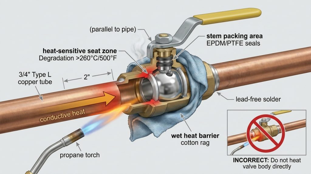
Ball valves are damaged during sweating when heat, pressure, or mechanical stress reaches parts that were not meant to be soldered. The solder cup needs enough heat for capillary flow, but the valve’s seat area, stem packing, O-rings, handle coating, and body joint need protection.
A ball valve shuts off flow by rotating a drilled ball through 90 degrees, and the seal depends on accurate contact between the ball and the seats. If you need the broader operating principle, RUITO’s explanation of how ball valve works in industrial piping systems gives useful background for understanding why seat damage matters.
Heat Travels Faster Than Many Installers Expect
Copper tube conducts heat quickly, and brass or bronze valve bodies also transfer heat toward the center section. If the flame is held on the body joint instead of the cup and tube, the temperature near the seats can rise before the solder has properly flowed.
The risk increases when the pipe is dirty, the joint clearance is wrong, too much flux is used, the torch tip is oversized, or the installer keeps heating after the solder has already filled the joint.
Damage May Not Show Until the Valve Is Used
A heat-damaged ball valve may look acceptable immediately after soldering. Problems often appear later as high operating torque, a handle that does not move smoothly, seepage around the stem, seat leakage, or a valve that no longer provides clean shutoff.
Do not assume a shiny solder bead proves the valve survived the process. The joint and the valve both need inspection.
Confirm the Valve Is Suitable Before You Heat It
Before heating, confirm that the valve is designed for solder-end installation and that its materials match the service. A valve with threaded, press, flanged, grooved, or welded ends should not be treated as a sweat-end valve just because it connects to a copper system somewhere in the assembly.
For copper joining, soldering is generally separated from brazing by filler-metal liquidus temperature; copper-alloy joining guidance notes that soldering uses filler metal below 450 °C, while brazing uses filler metal above that threshold. That distinction matters because a brazing-level heat input can expose a valve to much higher thermal stress than a normal soft-solder operation.
Match the Valve to the Fluid and Code Context
For potable water in the United States, the EPA’s lead-free rule states limits of no more than 0.2 percent lead for solder and flux, and no more than a weighted average of 0.25 percent lead for wetted surfaces of pipes, pipe fittings, plumbing fittings, and fixtures. For non-potable industrial systems, the correct material still depends on the medium, temperature, pressure, and required documentation.
The valve body material, seat material, stem seal, and solder alloy should be checked against the system specification before installation. This is especially important when the line carries glycol, chemicals, steam condensate, softened water, process water, or any medium that may affect brass, bronze, stainless steel, PTFE, EPDM, or other sealing materials.
Use This Pre-Heat Check
This table helps separate installation risks from product specification risks before the torch is lit.
| Checkpoint | What to Verify | Why It Matters | Reliable Basis |
|---|---|---|---|
| Joint fit | Tube and valve cup are clean, round, fully inserted, and not loose | Solder flow depends on capillary action, not on filling a large gap | The Copper Development Association notes capillary action is most effective at about 0.004 to 0.006 inch clearance in soldered copper joints |
| Potable-water compliance | Valve, solder, and flux are suitable for the local drinking-water requirement | A technically sound joint can still be unacceptable if materials are wrong | EPA lead-free limits include 0.2 percent lead for solder and flux and 0.25 percent weighted average for wetted surfaces |
| Fire exposure | Nearby combustibles, wall openings, insulation, and ceiling spaces are controlled | Valve damage is not the only risk during torch work | OSHA 29 CFR 1910.252 includes a 35 ft 10.7 m combustible-material benchmark for welding and cutting fire precautions |
| Valve construction | Manufacturer allows soldering, and valve position during heating is specified | Some valves require a particular ball position or disassembly procedure | Manufacturer IOM instructions should control the installation method |
| Heat-sensitive parts | Handle, packing, seats, O-rings, coatings, and nearby components are protected | These parts may fail before the metal body shows visible damage | Valve construction and seat material determine the heat-risk zone |
The table is not a substitute for the valve manufacturer’s installation manual. It is a way to catch the most common problems before they become hidden failures.
How to Sweat a Ball Valve Without Damaging It Step by Step
The safest way to sweat a ball valve without damaging it is to make the joint easy for solder to fill before heat is applied. Good preparation reduces torch time, which is the main advantage when the valve contains soft seats.
Prepare the Tube and Valve Cup
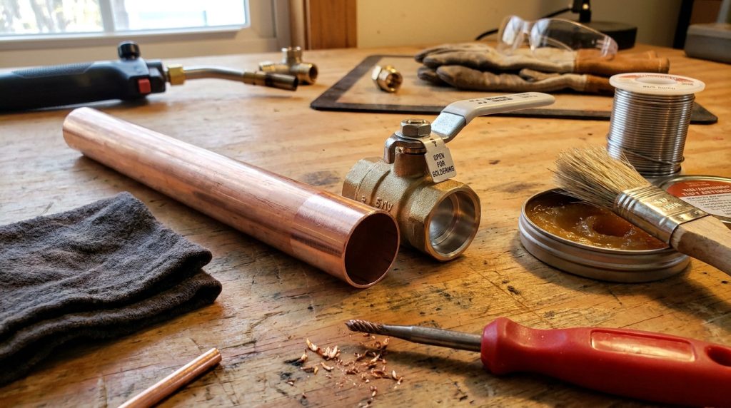
Cut the copper tube square, deburr the inside edge, and remove loose shavings. Clean the outside of the tube and the inside of the valve solder cup with suitable abrasive material until both surfaces are bright enough for soldering.
Apply only a thin, even coating of compatible flux to the cleaned surfaces. Excess flux can be pulled into the system, leave residue, or encourage overheating because the installer waits too long for a messy joint to behave correctly.
Protect the Valve Before Heating
Set the valve position according to the manufacturer’s instruction. If the instruction is unavailable, do not assume that a fully closed valve is safest; trapped air or moisture in the body cavity can expand during heating. Many installers use a partially open position to reduce trapped-pressure risk, but the valve-specific IOM should take priority.
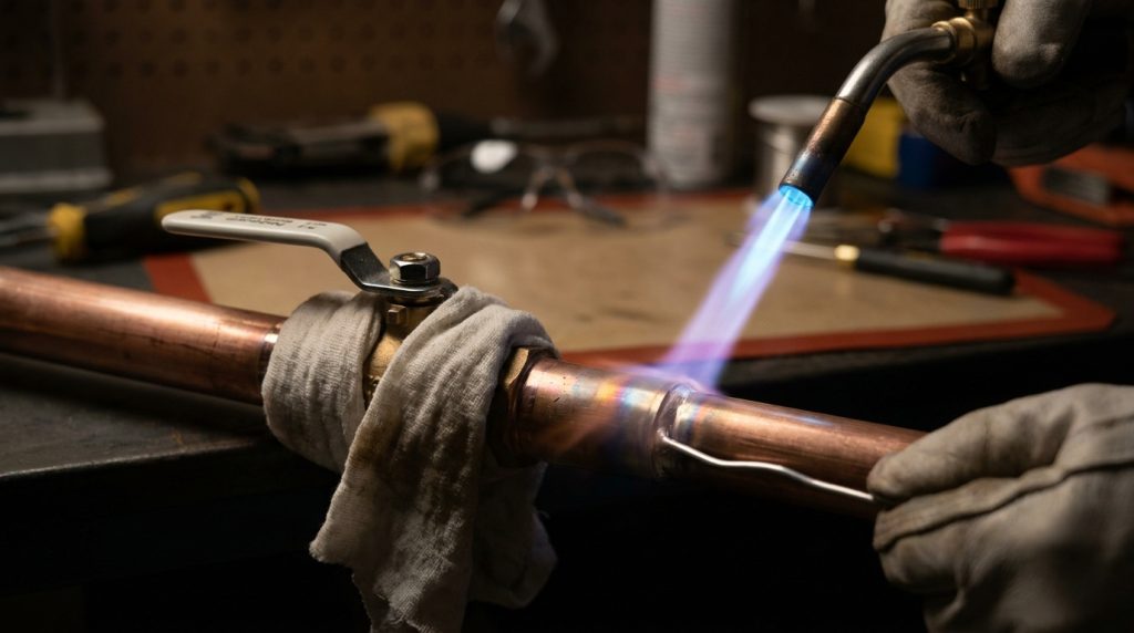
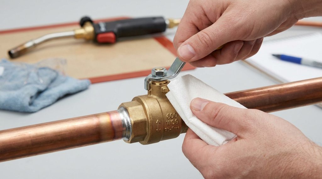
Remove the handle if it interferes with access or is vulnerable to heat. Wrap the center section of the valve with a damp heat barrier if allowed by the manufacturer, keeping the rag away from the flame. Support the pipe so the solder cup is not carrying pipe weight or side load during heating.
Heat the Tube First, Then the Cup
Direct the flame mainly at the copper tube near the socket, then sweep the heat around the solder cup. Keep the flame moving. Avoid pointing the hottest cone at the valve center section, stem area, body joint, or packing nut.
Touch solder to the joint opposite the flame. If the joint is ready, solder should be drawn into the gap rather than balling on the surface. Once a continuous solder line appears, remove heat and let the joint cool naturally.
Do not disturb the valve while the solder solidifies. Wiping the joint too aggressively, twisting the valve, or forcing the handle while hot can stress the connection or disturb internal sealing parts.
Control Heat Around Seats, Stem Packing, and Body Joints
Heat control is the core skill in this installation because the solder cup must get hot enough while the valve center stays cooler. This is where many otherwise careful installations fail.
Seat Material Has a Real Limit
Many ball valves use PTFE or PTFE-based soft seats, but the valve’s actual rating depends on the complete design, not PTFE alone. Published PTFE fluoropolymer data gives a broad temperature-resistance range of about -200 to 260 °C -328 to 500 °F, yet soldering heat at the valve socket can locally exceed what the assembled seat, preload, packing, lubricant, or body seal can tolerate.
That is why the practical question is not whether PTFE is a heat-resistant material in general. It is whether the assembled ball valve PTFE seat has been protected from unnecessary torch exposure during this specific joint.
Torch Size and Flame Direction Matter
Use a torch tip appropriate for the tube and valve size. An undersized flame can force long heating time, while an oversized flame can overheat the body before solder flows. The best flame pattern is controlled, moving, and focused on the soldering zone.
If solder does not flow after proper preheating, stop and reassess the joint. The problem may be dirty copper, poor fit, incompatible flux, moisture in the line, or insufficient access. Continuing to add heat is usually what damages the valve.
A Heat Sink Helps but Does Not Fix Poor Technique
A damp heat barrier can slow heat transfer into the valve center, but it should not be used as permission to overheat the cup. If the rag dries out, smokes, or pulls the flame toward the body, it is no longer helping.
For tight wall cavities, cabinet spaces, or prefabricated skids, consider whether soldering the valve in place is the right method. A threaded union, press connection, pre-soldered adapter, or different valve end connection may reduce heat exposure if the system specification allows it.
Inspect the Valve After Cooling
Inspection should confirm both the soldered joint and the valve function. A neat external bead is useful, but it does not prove the seat, stem packing, or ball surface stayed undamaged.
After the joint cools, clean flux residue from accessible surfaces. Cycle the handle gently from open to closed and back. The motion should feel smooth, without sudden binding, grinding, or unusual stiffness. If the handle was removed, reinstall it correctly and confirm that the handle position matches the ball position.
Then perform the pressure or leak test required by the project specification and local rules. For a small plumbing repair, that may be a water-pressure check. For an equipment package or industrial assembly, the test method should match the system design, valve rating, and customer requirement.
Warning Signs to Investigate
Look more closely if you notice any of these conditions:
- Solder did not fully draw around the joint.
- Flux residue is burnt, blackened, or glassy near the valve body.
- The handle is harder to turn than before heating.
- The stem area seeps during test pressure.
- The valve passes fluid when it should be closed.
- The body finish is discolored near the center section.
- Pipe alignment pulls the valve sideways after cooling.
A failed test does not automatically mean the solder joint is the only problem. The valve may have been overheated, mechanically stressed, contaminated with debris, or mismatched to the service.
When Replacement Is Safer Than Reworking the Joint
Replacement is usually safer when the valve itself shows signs of heat damage, seat leakage, stem seepage, or distorted operation. Reheating the same valve repeatedly can compound the original problem.
If the solder joint is poor but the valve still operates smoothly, a qualified installer may be able to remove and remake the joint depending on access, valve design, and project rules. If the valve leaks through the seat, binds after cooling, or has been overheated at the center body, treating the task as replacing a ball valve may reduce the chance of repeated failure.
Do Not Rework Blindly
Before rework, identify the cause. Was the pipe wet? Was the tube not deburred? Was the solder incompatible? Was the torch too large? Was the valve not supported? Was the valve body heated instead of the cup?
If the root cause is not corrected, the second attempt can be worse than the first. In production assemblies, document the failed joint and the corrective action so the same installation mistake does not move into repeated builds.
Project and Purchasing Checks for Sweat Ball Valves
For project teams, the installation method should be part of valve selection, not a field surprise. A sweat-end ball valve may be appropriate for copper water lines, HVAC branches, and compact equipment assemblies, but it is not automatically the best choice for every industrial service.
Confirm these items before purchasing or approving a sweat-end valve:
- End connection type and copper tube standard.
- Valve body material and wetted-surface material.
- Seat and stem seal material.
- Pressure and temperature rating for the actual medium.
- Potable-water or non-potable service requirement.
- Manufacturer soldering instructions.
- Whether the valve can be installed before nearby heat-sensitive components.
- Whether the line can be drained and cleaned before torch work.
- Required inspection or pressure test after installation.
This is also where procurement and installation teams need to communicate. A valve that looks inexpensive at purchase can become costly if it requires awkward soldering access, excessive heat exposure, or replacement after failed testing.
Conclusion
Sweating a ball valve without damaging it depends on preparation, heat direction, valve-position control, and post-installation inspection. The solder joint must reach the right temperature, but the valve center section should not be treated like a plain copper coupling.
RUITO’s position is simple: valve selection should make installation safer and clearer, with connection style, sealing material, and service conditions understood before heat reaches the pipe. If you are comparing ball valve options for a project, you can share the medium, pressure, temperature, end connection, installation method, and quantity through RUITO’s contact page so the discussion starts from the real operating conditions.
FAQ
Can I sweat a ball valve while it is closed?
Usually, you should not assume the closed position is correct. Valve manufacturers give different instructions, and trapped air or moisture can expand when heated, so follow the valve IOM before soldering.
Why does my ball valve leak after soldering?
The likely causes are overheating, damaged seats, stem-packing disturbance, poor solder flow, debris in the valve, or pipe stress after cooling. First identify whether the leak is at the solder joint, stem, body joint, or through the closed valve.
Should I remove the handle before sweating a ball valve?
Remove it if the manufacturer allows it and if it improves heat control or prevents handle damage. Keep track of the handle position so the valve orientation is correct after reassembly.
Is a wet rag enough to protect the valve?
A wet heat barrier can help, but it is not enough by itself. Proper cleaning, correct torch size, flame direction, short heating time, and pipe support matter just as much.
When should I choose another connection instead of a sweat valve?
Choose another connection when access is tight, nearby parts are heat-sensitive, the line cannot be fully drained, or the project requires a connection method better suited to inspection and replacement. Threaded, press, flanged, or welded-end valves may be more suitable depending on the system specification.