
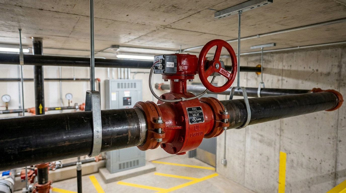
A sound butterfly valve fire protection specification starts with a listed indicating control valve that matches the water system, pipe interface, pressure, and supervisory requirements. A general water-service butterfly valve may open and close the line, yet still be unacceptable for a sprinkler, standpipe, or private fire-service main.
This distinction matters when a compact valve appears to fit the pipe but the submittal does not identify the approved model, supervisory-switch arrangement, or hydraulic loss. The practical solution is to treat the valve, operator, indication, switch, and approval record as one life-safety assembly—not as interchangeable catalog items.
What This Valve Does in a Fire Protection System
A fire-protection butterfly valve isolates the water supply to a system or defined section while giving operators a clear indication of whether the valve is open or closed. Turning the handwheel drives a gearbox and rotates the disc through approximately 90 degrees. The disc aligns with the flow when open and crosses the bore when closed.
In normal sprinkler or standpipe service, this valve is usually kept fully open. It is closed under an authorized impairment procedure for maintenance, testing, or sectional isolation, then reopened and returned to supervision. It is not the alarm valve, check valve, deluge valve, or waterflow detector, and it should not be selected as a routine throttling device simply because the disc can stop at intermediate angles.
The compact body is useful where a rising-stem gate valve would consume too much room. However, the disc remains in the waterway even when fully open. That makes the exact valve’s hydraulic-loss data part of the system decision, not a minor catalog detail.
Fire-Protection Listing Is Not a Fire-Safe Rating
A butterfly valve for fire-protection service and a fire-safe butterfly valve answer two different engineering questions. UL 1091 covers butterfly valves intended for piping that supplies water for fire-protection service. The submittal must still show that the exact model, size, pressure rating, end connection, and accessories fall within the required listing or approval.
By contrast, ISO 10497 specifies fire type-testing for isolation valves, including assessment of through-seat leakage, external leakage, operability, and other behavior during and after a defined fire test. That qualification addresses valve integrity under fire exposure; it does not by itself establish suitability as an indicating, supervised control valve in a sprinkler system.
This is the first screening question for any RFQ: does “fire” refer to a water-based fire-protection system, a process-valve fire test, or both? Do not accept “fire rated,” “fire approved,” or “UL/FM” as complete answers. Ask for the approval certificate or database entry and confirm that its scope matches the quoted configuration.
Supervision Reports Position; It Does Not Move the Valve
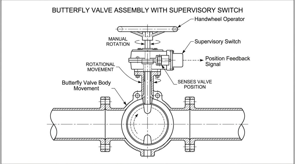
A supervisory or tamper switch reports that the valve has moved away from its normal position; it does not actuate the disc. In a typical assembly, the handwheel turns the gearbox, while a cam or internal mechanism changes the state of electrical contacts as the valve begins to close. The fire alarm control unit then receives a supervisory signal.
That signal is also different from a waterflow alarm. A supervisory signal says the valve or monitoring circuit is off normal and needs investigation. A waterflow device reports water movement associated with an operating system or test. If remote opening or closing is required, specify an actuator package and control logic separately; do not treat a tamper switch as an actuator.
The mechanical and electrical interfaces must be reviewed together. Confirm the normal position, switch contact arrangement, circuit rating, wiring diagram, conduit entry, enclosure suitability, required signal point, and panel description. A detailed tamper-switch installation and test procedure can then be tied to the actual approved valve assembly and local acceptance criteria.
Match Connection, Rating, and Flow Data to the System
The correct body style is the one that matches the approved piping system, maintenance plan, available space, and documented valve limits. The connection name alone is not enough.
Use this comparison to screen the options before checking the model-specific listing:
| Connection | Practical fit | Items to verify before approval |
|---|---|---|
| Grooved | Compact sprinkler risers and branch isolation where an approved grooved piping system is used | Pipe outside diameter, groove specification, coupling compatibility, working pressure, operator clearance, and approval scope |
| Wafer | Flanged piping where a short face-to-face dimension is valuable | Flange standard, bolt pattern, disc clearance, centering method, gasket restrictions, and whether removal requires shutdown on both sides |
| Lug | Flanged piping that needs independent bolting on each side | Tapped-lug thread, bolt length, flange drilling, directional limits, and explicit dead-end pressure rating |
| Flanged | Larger mains or layouts that call for a rigid flanged connection | Flange standard and class, face-to-face dimension, support loads, installation envelope, and approved size range |
Grooved does not automatically mean listed for every fire system, and lug does not automatically mean safe for dead-end service at full rated pressure. For a deeper mechanical comparison, check the actual piping condition against the lugged-versus-wafer selection criteria, then return to the fire-protection approval record for the final decision.
Next, verify maximum working pressure, maximum differential pressure, temperature, water quality, and indoor or outdoor exposure. Match the body, disc, stem, seat, coating, and fasteners to those conditions. Request the manufacturer’s equivalent length, K-factor, Cv, or other approved loss data for the exact valve and include it in the hydraulic calculation; do not substitute a generic butterfly-valve value when the actual model is known.
Build a Model-Specific Submittal
A reliable submittal identifies one traceable valve assembly rather than combining the strongest claims from several brochures. At minimum, lock the following information before purchase:
- System duty and location: sprinkler riser, standpipe, fire-pump connection, sectional isolation, or private fire-service main; normally open or normally closed.
- Code and acceptance basis: adopted codes, project specification, authority having jurisdiction, and the exact required listing or approval.
- Valve identity: manufacturer, series, model, nominal size, working pressure, flow direction limits, and nameplate marking.
- Pipe interface: grooved, wafer, lug, or flanged end; pipe outside diameter; groove or flange standard; face-to-face dimension; and required bolting or coupling.
- Materials and environment: body, disc, stem, seat, coating, fasteners, water condition, temperature, indoor/outdoor location, and enclosure rating.
- Operation and supervision: gearbox, visible position indication, switch quantity and contact form, electrical rating, wiring diagram, conduit connection, and signal description.
- Performance evidence: model-specific approval document, hydraulic-loss data, pressure-test requirements, dimensional drawing, installation instructions, and inspection records.
RUITO’s published industrial butterfly valve range covers DN25–DN3000, PN10–PN25, wafer, lug, and flanged bodies, plus several body, disc, and seat materials depending on configuration. Those figures are a preliminary manufacturing envelope, not proof that every configuration is accepted for fire-protection service. A fire-system quotation must be narrowed to the project-required approval, exact model scope, and documented accessories before it is submitted for acceptance.
This boundary prevents a common procurement error: approving a mechanically suitable valve while leaving the life-safety acceptance path unresolved until delivery.
Commission the Mechanical and Supervisory Functions Together
Commissioning must prove that the valve operates correctly, the switch changes state at the required point, and the panel interprets the correct signal. A visual check of the OPEN indicator alone cannot establish all three.
Before handover, complete these actions under the approved impairment and testing procedure:
- Match the nameplate, tag, model, size, pressure rating, and approval details to the approved submittal.
- Check flow direction, pipe alignment, disc clearance, coupling or bolting, gearbox orientation, accessibility, and handwheel clearance.
- Fully open the valve and confirm both the mechanical indication and the normal panel condition.
- Move the valve toward closed and verify that the correct supervisory point appears at the fire alarm control unit within the criterion set by the adopted code and authority.
- Confirm the signal remains off normal while the valve remains displaced, then fully reopen the valve and verify that the panel resets correctly.
- Record the test, restore all covers and circuits, identify the system area served, and confirm that the valve is left in its required normal position.
Detailed flange preparation, centering, tightening, and clearance checks should follow the approved drawing and the relevant butterfly valve installation guidance. After acceptance, use the locally adopted edition of NFPA 25, the project documents, and the authority’s requirements to set inspection, testing, maintenance, and impairment procedures. Do not copy a frequency from a generic article without checking the governing edition.
Specify the Valve as Part of the Life-Safety System
The safest butterfly valve fire protection decision joins six items: system duty, model-specific approval, pressure and hydraulic data, pipe interface, supervised position, and verified handover. If any one is missing, a valve that looks correct on the pipe may still create an acceptance or readiness problem.
RUITO can review your datasheet, pipe standard, pressure, materials, required approvals, supervisory interface, and documentation needs against its manufacturing scope. Send the full specification through contact RUITO’s engineering team so the compliance boundary and technical package can be clarified before quotation.
FAQ
Can a supervisory switch be added to an existing valve?
Only when the switch, mounting arrangement, and valve are approved for that combination and the installation follows the device instructions. A field-added switch that changes electrical state is not automatically an accepted supervised fire-protection assembly.
Is a grooved butterfly valve always best for sprinklers?
No. Grooved valves are compact and convenient when they match the approved grooved piping system, but wafer, lug, or flanged designs may better fit another approved layout. Select by the piping interface, pressure, approval scope, maintenance plan, and available clearance.
What should staff do when a tamper signal appears?
Treat it as an off-normal readiness condition and investigate the actual valve, switch, wiring, and panel label under the facility’s fire-protection procedure. Do not silence the condition by bypassing the switch, and do not operate the valve without the required authorization and impairment controls.
Does a lug body guarantee dead-end service?
No. A lug body provides independent bolting, but dead-end suitability depends on the specific valve design, pressure differential, seat direction, bolting, and manufacturer rating. Require an explicit dead-end rating for the quoted model and installation direction.