
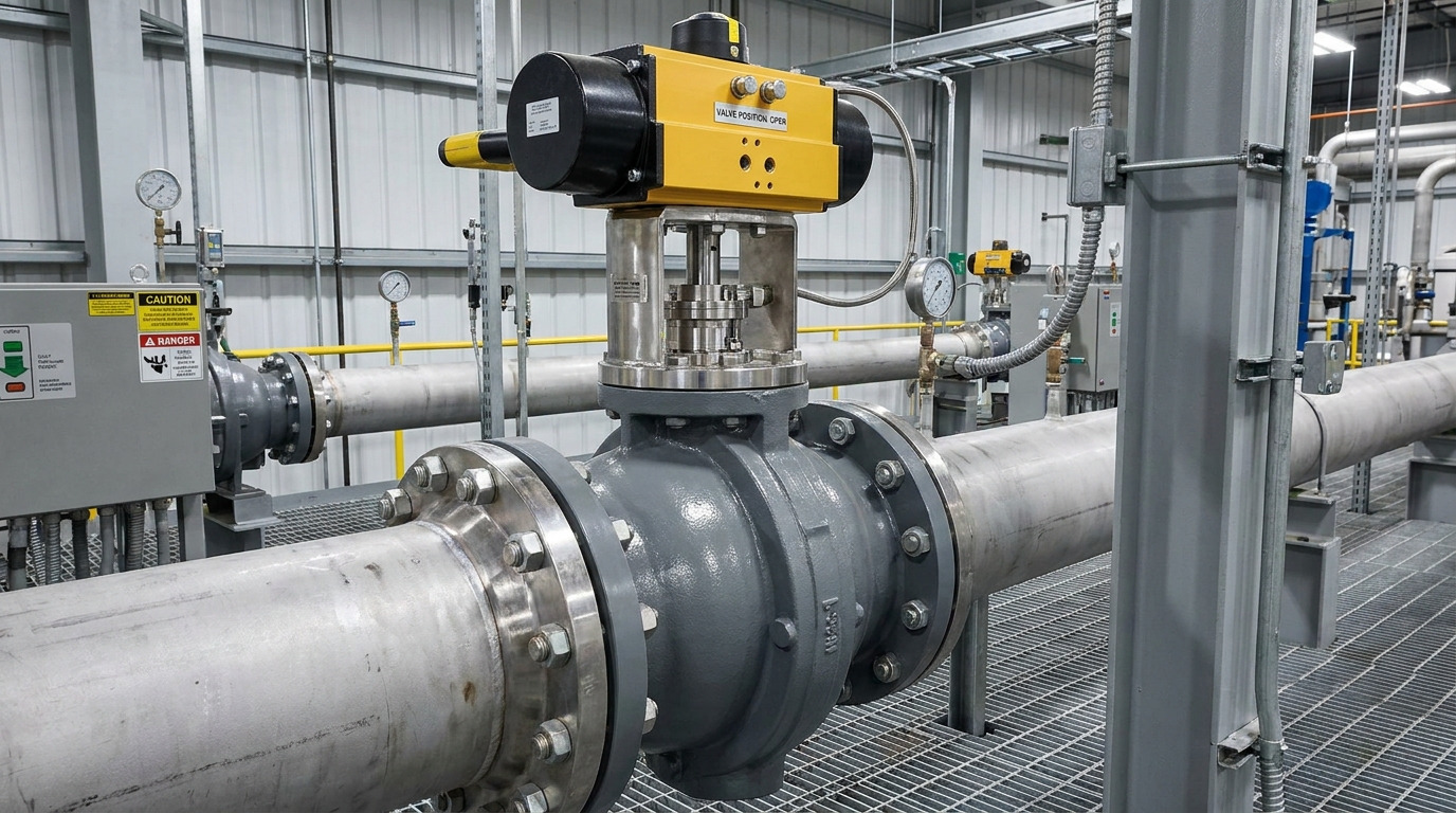
A butterfly valve stem is the torque-carrying shaft that links the operator to the disc, supports controlled disc rotation, and passes through the valve pressure boundary without allowing process fluid to escape. A valve may look correct from its body, seat, and pressure class yet still bind, leak, or lose disc control if the stem system is mismatched. When reviewing an industrial butterfly valve section and parts diagram, treat the stem as an assembly of interfaces rather than a standalone metal bar.
What the Stem Does Inside a Butterfly Valve
The stem performs three jobs at the same time: it transmits operating torque, locates the disc, and works with seals and bearings at the body penetration. A handle, gearbox, or actuator turns the stem through a quarter turn so the disc can isolate or regulate flow.
The clean engineering definition is this: the stem is the mechanical and sealing interface between the dry operating equipment and the wetted disc assembly. That definition explains why torque, corrosion, runout, surface condition, bearings, packing, and retention all matter.
Stem Architecture: Trust the Drawing, Not the Label
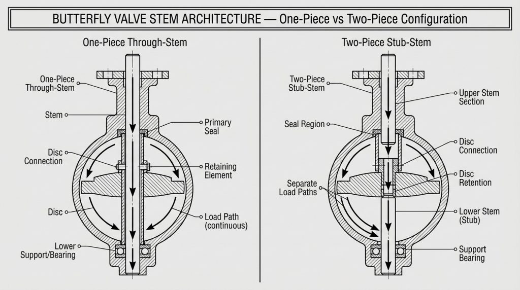
A label such as “one-piece,” “through-stem,” “split-stem,” or “two-piece” is not enough to establish the actual load path. Suppliers do not always use these terms consistently, so request a sectional drawing that shows the stem segments, disc hubs, bearings, fasteners, seals, and axial retainer. A verified drawing is more useful than a catalog label.
One-piece or through-stem designs
A one-piece stem is a continuous shaft passing through or across the disc, normally with support near the top and bottom of the body. It gives a continuous torque path, but reliability still depends on the minimum shaft section, bearing span, and disc connection.
Two-piece or stub-stem designs
A two-piece arrangement uses an upper drive stem and a lower stub shaft. The upper segment transmits torque while the lower segment supports the disc, increasing the importance of the upper connection and alignment between both supports.
Architecture does not determine corrosion exposure by itself. In some resilient-lined valves, the seat or liner isolates most of the stem from the medium; in other designs, portions of the stem, pins, keys, or disc hubs are wetted. Mark every wetted surface on the section drawing before selecting material.
Follow the Entire Torque Path
Stem capacity is only reliable when every link from the operator to the disc can carry the required torque under the same service condition. The path normally runs through the actuator output, coupling or adapter, stem top, minimum stem section, disc drive feature, and disc hub.
Square, double-D, keyed, splined, and pinned connections transfer load differently. A keyway or pin hole reduces the net section, a loose fit can add impact and fretting, and shallow coupling engagement can concentrate load. Check these details on the drawing rather than inferring capacity from nominal stem diameter.
Bearings or bushings keep the stem aligned under pressure and flow forces, while thrust components control axial movement. Worn or off-center supports can bend the stem, wear packing unevenly, and make the disc rub the seat.
Choose Stem Material for Strength and Exposure
Stem material must satisfy mechanical strength, corrosion resistance, surface durability, and compatibility with the bearing and seal system. A material name alone is incomplete; the specification should also identify heat-treatment condition, coating where applicable, hardness requirements, and which surfaces contact the process.
This comparison shows the engineering tradeoffs that should be resolved rather than relying on a single “best” grade.
| Material family | Useful characteristics | Points to verify |
|---|---|---|
| Plated carbon or alloy steel | Cost-effective strength for controlled, non-corrosive exposure | Coating type and thickness, damage risk at seals or keys, and whether any uncoated area is wetted |
| 304 or 316 stainless steel | General corrosion resistance and good toughness | Required diameter for torque, chloride severity, crevice exposure, and galling against stainless mating parts |
| 410 or 420 stainless steel | Higher hardness and strength with useful wear resistance | Heat treatment, final hardness, corrosion limits, and surface finish at seals and bushings |
| 17-4PH stainless steel | High strength with corrosion resistance for compact or high-torque stems | Heat-treatment condition, hardness records, environmental compatibility, and machining at notches |
| Duplex stainless steel | Higher strength with improved resistance in many chloride services | Exact grade, process chemistry and temperature, material verification, and bearing-pair compatibility |
Judge the weakest combined condition. Corrosion can reduce the net section of a strong stem, while a corrosion-resistant grade can still twist at an undersized keyway, pin hole, or minimum diameter. Also check the mating bushing or drive insert for galling risk.
Separate Sealing, Guidance, and Stem Retention
The stem seal, bearing system, and axial retainer perform different functions and are not interchangeable. For a broader review of elastomers, PTFE, packing, and seat duties, see the butterfly valve sealing guide.
The following table separates each function and its typical failure signal.
| Component group | Primary function | Typical evidence of a problem |
|---|---|---|
| O-rings, packing, or lip seals | Maintain the pressure boundary around the rotating stem | External leakage, damaged seal contact area, or uneven packing compression |
| Radial bushings or bearings | Guide the stem and resist side load | Rising torque, runout, uneven wear, or disc-to-seat rubbing |
| Thrust washer or thrust bearing | Control axial position of the stem and disc | Axial movement, altered disc position, or changing seat contact |
| Shoulder, retaining ring, plate, or other retainer | Prevent unintended stem displacement or ejection | Visible movement, loose hardware, or loss of positive retention |
| Packing gland | Apply controlled compression to adjustable packing | Leakage when too loose; excessive friction and heat when over-tightened |
A packing gland should compress packing, not serve as the sole axial retainer. Likewise, tightening packing may temporarily reduce leakage but will not correct a scored stem, worn bushing, bent shaft, or missing retention feature.
Match the Stem to the Actuator, Not Just the Flange
An actuator flange match does not prove that the stem, adapter, and actuator form a suitable package. ISO 5211:2026 addresses attachment flange dimensions, driving-component dimensions, and reference interface torque values. It does not replace the valve maker’s operating-torque data or a mounting-kit check.
Confirm the stem-top shape and across-flat dimension, key size, engagement depth, coupling material, bracket rigidity, travel stops, and allowable interface torque. Then compare the actuator’s output at the relevant supply condition with breakaway, running, and closing torque at the maximum specified differential pressure and temperature. A butterfly valve torque chart should state its test conditions before it is used for sizing.
ISO 5115:2023 treats the valve, actuator, and mounting kit as an assembled part-turn package. Standard geometry supports interchangeability, but it does not guarantee torque capacity, alignment, or control accuracy.
Diagnose Stem Problems by Location and Evidence
Stem troubleshooting should locate the failed interface before any part is replaced. Isolate and depressurize the line under the approved lockout procedure before removing an actuator, retainer, packing, or internal part.
Use the symptom pattern below to choose the next inspection.
| Symptom | Likely location | Checks and next action |
|---|---|---|
| Operator moves but the disc does not follow | Coupling, key, spline, pin, or disc hub | Stop forcing the operator; compare indicated and actual position, then inspect drive engagement and fasteners after safe isolation |
| Torque rises sharply through mid-travel | Stem alignment, bushings, debris, or pipe-induced distortion | Record torque versus angle; check flange alignment, stem runout, bushing wear, and internal interference |
| Leakage appears around the stem | Packing or O-ring, stem surface, gland alignment | Record pressure, temperature, and medium; inspect seal compression and the stem contact surface instead of repeatedly tightening the gland |
| Actuator trips or stalls near closing | Seat interference, incorrect stops, high differential pressure, or inadequate torque margin | Verify disc clearance, travel stops, service torque data, and actuator output at the actual supply condition |
| Fault returns soon after a new seal is installed | Bent stem, worn guide, rough seal surface, or excessive side load | Measure runout and clearances; replace or correct the damaged support component before installing another seal |
A torque increase at the same angle suggests local interference or damage; a broad increase across travel more often indicates packing load, bearing friction, corrosion, or misalignment. A structured butterfly valve maintenance plan should preserve these observations.
Use a Stem Specification and Inspection Checklist
A useful stem specification identifies the service, geometry, interfaces, and evidence required for approval. Include the following items on the drawing, data sheet, or RFQ:
- Medium composition, solids, normal and maximum temperature, pressure, maximum differential pressure, and operating frequency
- One-piece or two-piece section drawing with every wetted surface identified
- Stem material standard, exact grade, heat-treatment condition, coating, hardness, and corrosion allowance where required
- Minimum diameter and net section at keyways, pin holes, threads, shoulders, and other discontinuities
- Disc connection type, engagement length, pin or key details, and replaceability
- Radial bearings, thrust components, stem seals, packing adjustment, and positive axial-retention method
- Actuator flange, stem-top geometry, coupling dimensions, engagement depth, bracket arrangement, and allowable interface torque
- Breakaway, running, and closing torque with test conditions, safety basis, travel stops, and actuator output condition
- Material certificate, dimensional and runout report, assembly torque record, shell test, seat leakage test, and functional-cycle record as required by the project
For RUITO butterfly valve orders, published production controls include shaft-concentricity verification, alignment and disc-contact checks, and torque checks at 25%, 50%, and 100% travel. Available records include material certificates, dimensional reports, torque logs, and pressure/leakage test documents. These distinguish a verified assembly from one described only by grade and nominal diameter.
A Reliable Stem Is an Assembly Decision
A reliable butterfly valve stem is one whose material, geometry, joints, bearings, seals, retainer, and actuator interface remain compatible at the most demanding specified load. Start with the section drawing, follow the torque path, mark the wetted boundary, and require evidence for the dimensions and tests that control performance.
If you are reviewing a new valve package or investigating repeated stem leakage, high torque, or lost disc motion, contact the RUITO engineering team with the service conditions, valve drawing, actuator data, and observed symptoms.
Frequently Asked Questions
Is a butterfly valve stem the same as a shaft?
Yes, “stem” and “shaft” commonly describe the same torque-transmitting component. Follow the item numbers on the manufacturer’s sectional drawing because parts lists may use either word.
Does butterfly valve stem orientation matter?
It can matter, but no orientation suits every design and service. Disc weight, solids, bearing loads, drainage, access, and the manufacturer’s instructions determine the preferred position.
Is a stem extension the same as a longer valve stem?
No, a stem extension is an external drive component for a relocated operator. It needs support and alignment so the extension, gearbox, or actuator does not side-load the internal stem.
Can a butterfly valve stem be replaced separately?
Sometimes, if the design has a replaceable stem and matched parts are available. Inspect the disc hub, drive features, bushings, seals, and retainer, then repeat the required dimensional, torque, shell, and seat-leakage checks.