
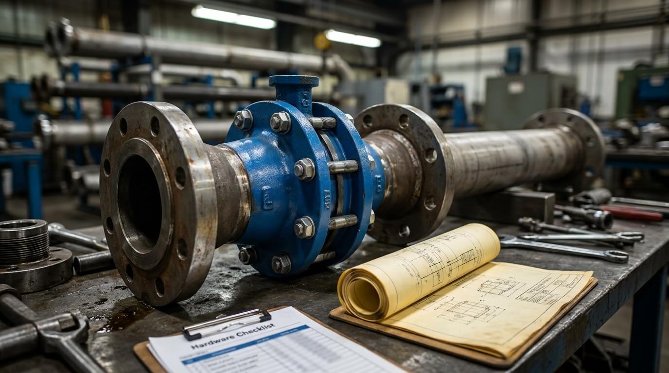
Use this lug butterfly valve bolt chart to identify the ASME Class 150 bolt diameter and quantity, then confirm the thread pitch and cap-screw length on the valve drawing before ordering. The flange standard fixes the drilling pattern, but the valve body fixes how the fastener enters the lug and how much thread it can engage.
That distinction prevents the most common fit error: a fastener can match the flange hole yet still be too long, too short, or threaded incorrectly for the valve. It also explains why a through-bolt length taken from a wafer-valve table cannot be copied into a lug-valve order.
This article gives you a Class 150 reference chart, a length stack-up method, and release checks for procurement and installation. If the valve specification is still open, compare the available industrial butterfly valve configurations before finalizing the hardware.
What the Chart Controls and What It Does Not
A lug butterfly valve bolt chart should control the flange pattern and identify the hardware interface, but it should not be treated as a universal cap-screw length or torque schedule. A useful chart separates standard data from valve-specific data.
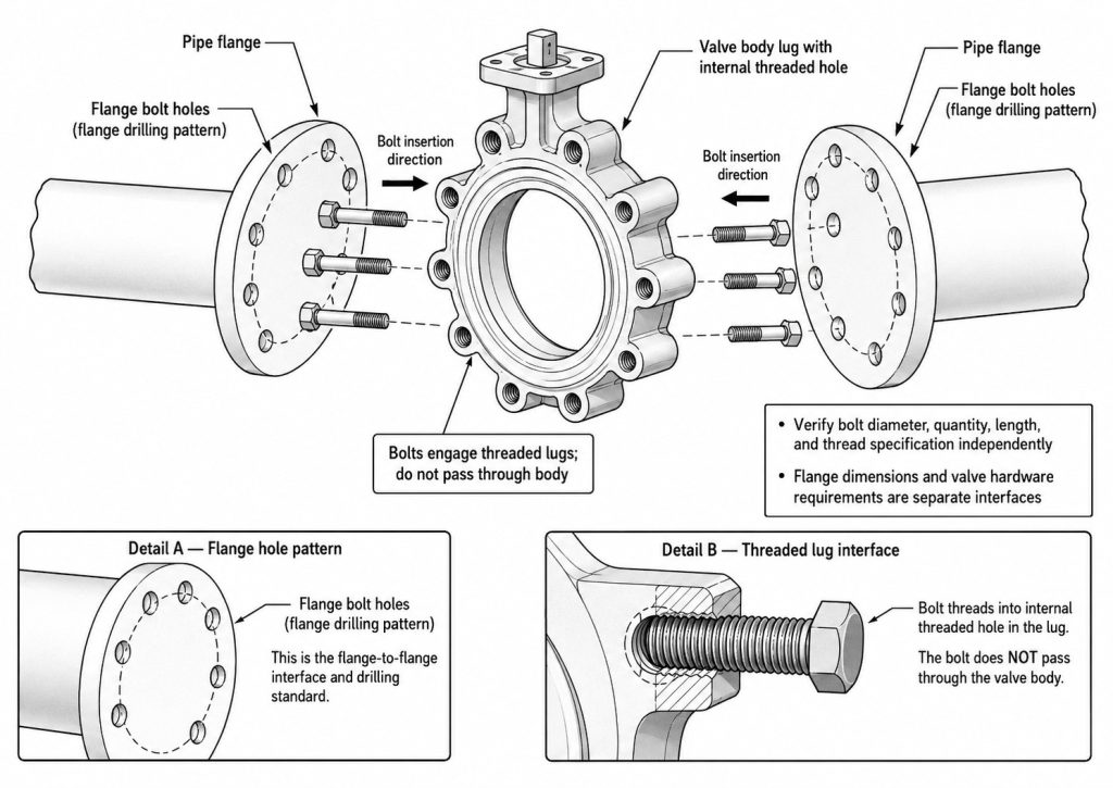
The flange standard controls the nominal size, pressure class, bolt-hole count, bolt-hole diameter, bolt circle, and nominal bolt diameter. The approved valve drawing controls the lug thread, usable tapped depth, body thickness, whether the hole is blind or through-tapped, and the permitted penetration from each side.
The installed arrangement matters too. A fully lugged body normally uses a separate set of cap screws through each pipe flange and into the valve body. A wafer body normally uses fasteners that pass across the valve body, so the length basis and quantity convention differ. Review the wafer-versus-lug selection differences before using one style’s hardware list for another.
ASME Class 150 Lug Butterfly Valve Bolt Chart
The chart below gives common ASME Class 150 flange-drilling values for NPS 2 through NPS 24 lug butterfly valves. ASME B16.5-2025 covers flange dimensions, tolerances, bolting, gaskets, and joints for NPS 1/2 through NPS 24 across several pressure classes, including Class 150.
| Valve size | Nominal bolt diameter | Holes per flange | Cap screws for two flanges* | Flange hole diameter | Bolt circle diameter |
|---|---|---|---|---|---|
| NPS 2 | 5/8 in | 4 | 8 | 3/4 in | 4-3/4 in |
| NPS 2-1/2 | 5/8 in | 4 | 8 | 3/4 in | 5-1/2 in |
| NPS 3 | 5/8 in | 4 | 8 | 3/4 in | 6 in |
| NPS 4 | 5/8 in | 8 | 16 | 3/4 in | 7-1/2 in |
| NPS 5 | 3/4 in | 8 | 16 | 7/8 in | 8-1/2 in |
| NPS 6 | 3/4 in | 8 | 16 | 7/8 in | 9-1/2 in |
| NPS 8 | 3/4 in | 8 | 16 | 7/8 in | 11-3/4 in |
| NPS 10 | 7/8 in | 12 | 24 | 1 in | 14-1/4 in |
| NPS 12 | 7/8 in | 12 | 24 | 1 in | 17 in |
| NPS 14 | 1 in | 12 | 24 | 1-1/8 in | 18-3/4 in |
| NPS 16 | 1 in | 16 | 32 | 1-1/8 in | 21-1/4 in |
| NPS 18 | 1-1/8 in | 16 | 32 | 1-1/4 in | 22-3/4 in |
| NPS 20 | 1-1/8 in | 20 | 40 | 1-1/4 in | 25 in |
| NPS 24 | 1-1/4 in | 20 | 40 | 1-3/8 in | 29-1/2 in |
*The total assumes a conventional fully lugged valve installed between two flanges, with a separate cap screw entering each lug from each side. Confirm how the valve supplier defines quantity.
Use the table to check physical flange compatibility, not to release cap-screw length. NPS 3-1/2 and NPS 22 are not shown because they are not common catalog sizes for many lug butterfly valve ranges; request the actual valve drawing if either appears in your project.
Read Diameter, Quantity, and Thread as Separate Fields
You should read bolt diameter, quantity, and lug thread as separate fields because each prevents a different ordering error. A matching nominal diameter does not prove that the thread series or hardware count is correct.
First, determine whether the chart lists holes per flange or total cap screws for the complete valve. For a conventional fully lugged body, eight holes per flange normally mean sixteen cap screws for a two-flange installation. If a purchase order simply says “quantity 8,” one side may arrive without hardware.
Next, obtain the internal thread callout from the drawing. The flange hole is a clearance feature; it does not define the tapped thread inside the valve lug. For example, the nominal bolt diameter in the table may be correct while the thread pitch, thread form, or fit class is wrong. Put the full thread designation on the hardware order rather than ordering by diameter alone.
Calculate Cap-Screw Length from the Actual Stack
Cap-screw length must be calculated from the installed stack and checked against the usable tapped depth. The required under-head length is the sum of the flange thickness at the bolt hole, any compressed gasket allowance, washer thickness, and the effective thread engagement required by the approved design.
Required under-head length = flange thickness + gasket allowance + washer thickness + specified effective thread engagement
Use this as a worksheet, not as permission to invent the engagement value. The valve drawing or project bolting specification must define the acceptable engagement and the usable depth after allowing for chamfers, incomplete threads, and bottom clearance.
Check the lug construction before rounding to an available fastener length:
- For a blind tapped lug, confirm that the selected screw cannot bottom before it clamps the flange.
- For a through-tapped or opposing arrangement, confirm that screws entering from opposite sides cannot meet inside the lug.
- If a washer is added or removed, recalculate both engagement and bottoming clearance.
- If the valve uses a resilient seat as the flange seal, do not add a separate gasket thickness unless the valve instructions permit that gasket.
The full lug-type butterfly valve installation should follow the approved body drawing because disc clearance, flange alignment, and seat compression can affect the same hardware decision.
Release Hardware Only After Five Fit Checks
Release the hardware only when the flange data, valve data, and installation stack agree. A chart lookup is complete only after the following five checks pass.
- Standard and class: The pipe flange, valve drilling, and chart all state the same standard, edition basis, and pressure class.
- Pattern: The hole count, nominal diameter, hole diameter, and bolt circle match the mating flange and approved drawing.
- Thread: The cap-screw diameter, pitch, thread form, and fit match the tapped lugs.
- Length: The under-head length provides the specified engagement without bottoming, opposing-screw contact, or missing clamp load.
- Quantity and documentation: The order states quantity per side and total quantity, and the approved valve drawing is attached to the hardware release.
For RUITO butterfly valve orders, the product documentation can include engineering drawings, and dimensional inspection can cover the flange-drilling pattern. For fit-critical replacements or mixed-standard projects, ask for the approved drawing and dimensional inspection report before releasing fasteners. This turns “check with the supplier” into a defined document requirement that procurement and site teams can verify.
Keep Torque Out of a Generic Bolt Chart
A generic bolt chart should not assign one torque value by diameter alone. The required assembly load changes with fastener grade, material, coating, lubrication, gasket design, flange condition, and the project’s target bolt stress.
ASME PCC-1-2022 treats pressure-boundary bolted flange assembly as a controlled procedure that considers the joint, gasket, fasteners, and assembly method. Use the approved project procedure or valve instructions for tightening stages, sequence, and final torque; do not copy a value from a different material or lubrication condition.
Before tightening, clean the mating faces, center the valve without using bolts to force misaligned piping into position, and start every cap screw by hand. Bring both flanges in evenly using a cross-pattern sequence, check that the disc has clearance, and complete the staged tightening procedure. If a separate gasket is required, confirm its type and placement through the butterfly valve gasket selection requirements rather than adding one automatically.
Stop if a screw becomes tight before the flange is clamped, if one flange closes faster than the other, or if the valve disc rubs after snugging. Those signals point to bottoming, thread mismatch, misalignment, or incorrect stack thickness; more torque will not correct the cause.
Know When the Class 150 Chart No Longer Applies
Do not use this Class 150 table when any governing input changes. A similar nominal size does not make different flange systems interchangeable.
- Class 300 or another ASME class: The bolt diameter, hole count, flange thickness, and bolt circle may change. Use the correct pressure-class table and a matching valve drawing.
- EN, JIS, AWWA, or another flange standard: Use the specified metric or national drilling data and confirm the lug thread system. Do not substitute inch hardware merely because the NPS and DN labels appear close.
- Semi-lug, partial-lug, or special body: The number and function of the lugs may differ from a fully lugged valve, so the “two times holes per flange” rule may not apply.
- Dead-end service: A lug body is not automatically rated to hold full differential pressure with one downstream flange removed. Confirm the permitted pressure, direction, seat retention, and one-sided bolting arrangement on the data sheet.
- Nonmetallic or nonstandard flanges: Flange stiffness, washer requirements, allowable load, and gasket behavior may require a project-specific assembly procedure.
If any of these conditions appears, mark the generic chart “reference only” and hold the hardware order until the governing drawing and specification agree.
Turn the Chart into a Verified Hardware Order
The safest use of a lug butterfly valve bolt chart is to verify the flange pattern first, then complete the order with valve-specific thread and length data. Record the standard, class, size, diameter, full thread designation, quantity per side, total quantity, under-head length, washer and gasket assumptions, lug type, and drawing revision on one release sheet.
RUITO can review those inputs against the proposed valve configuration and prepare the drawing basis for your purchase. Send the line size, flange standard and class, existing flange dimensions, gasket and washer details, service conditions, and any site measurements through contact our engineering team before ordering the hardware.
FAQ
Can I use an ASME flange bolt chart for lug cap-screw length?
No. The flange chart can establish the hole pattern and nominal bolt diameter, but it does not define the valve body’s usable tapped depth. Calculate length from the actual stack and confirm it on the approved valve drawing.
Does a lug valve always need twice the flange bolt count?
Not always, but a conventional fully lugged valve between two flanges normally uses one cap screw per flange hole on each side. Semi-lug, partial-lug, and special bodies can use a different arrangement, so check whether the listed quantity is per side or total.
Can the same chart be used for Class 300 or PN16 flanges?
No. Pressure class and flange standard can change the bolt circle, hole count, diameter, flange thickness, and thread system. Use the chart for the exact standard and rating shown on the piping and valve documents.
Do lug butterfly valves require a separate flange gasket?
It depends on the valve design. Some resilient-seated butterfly valves use the seat face as the flange seal, while other designs require a specified gasket. Follow the valve instructions because an unapproved extra gasket can change alignment, seat compression, and cap-screw length.