
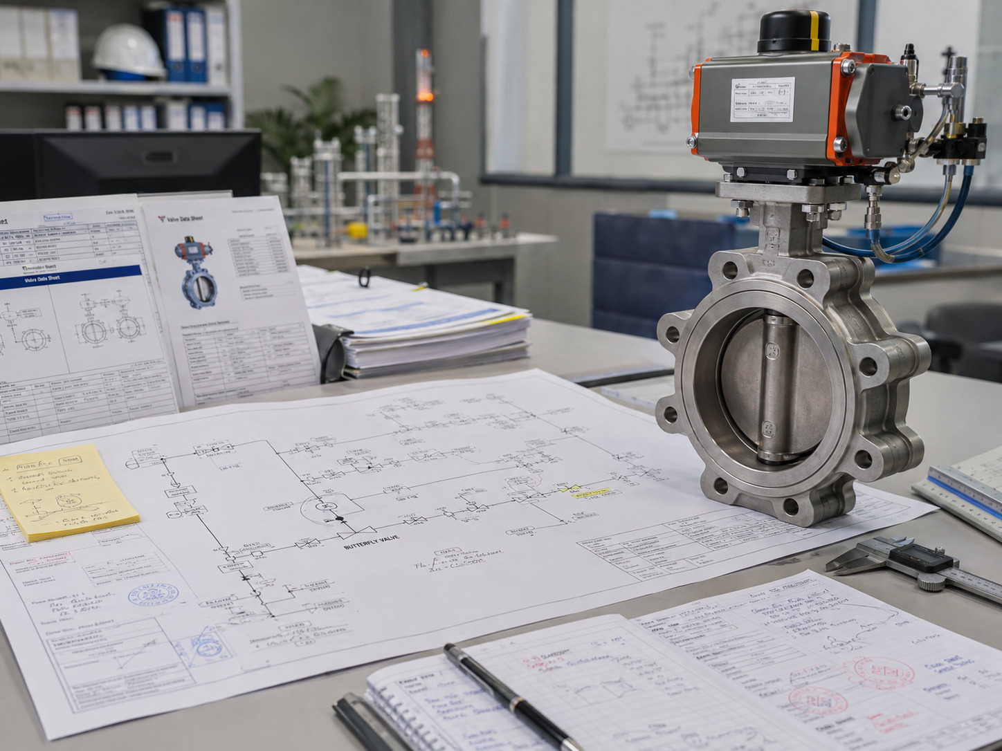
Read a butterfly valve P&ID symbol by combining its base shape with the project legend, tag, actuator notation, line data, and valve schedule—not by relying on the icon alone. A common symbol can identify a quarter-turn disc valve at a particular point in the process, but it usually cannot prove the body pattern, materials, pressure rating, fail action, or live valve position. If you are matching a drawing to real hardware, the available industrial butterfly valve configurations show how many different designs can sit behind one basic symbol.
That distinction matters during design review and purchasing. An engineer may recognize the symbol correctly and still release the wrong valve if the drawing, schedule, and datasheet do not agree. The method below separates what the P&ID shows from what the project documents must confirm.
Start With the Base Butterfly Valve Symbol
A common butterfly valve symbol shows a valve body with a line through its center to suggest the rotating disc. The disc is the defining mechanical clue: a butterfly valve controls or isolates flow by turning this disc through a quarter turn.
However, the exact graphic is not universal. Some libraries use a circular body and central line, while others use a stylized valve outline with a disc mark. Line weight, orientation, fill, and nearby connection marks may also change between owners, industries, and CAD libraries. Treat the shape as an identification cue, not as a complete specification.
The clean engineering judgment is this: the base symbol normally identifies valve type and location; it does not, by itself, identify the exact valve construction or operating condition.
Let the Project Legend Overrule Generic Charts
The project legend or lead sheet is the final authority for interpreting a butterfly valve P&ID symbol. Generic charts are useful for recognition, but they cannot override the drawing standard adopted by the plant, EPC, package vendor, or project.
ISO 10628-2:2012 defines graphical symbols for chemical and petrochemical industry diagrams and remains current after its 2024 confirmation. ANSI/ISA-5.1-2024 addresses uniform symbols and identification for instrumentation and control while allowing alternative symbolism methods for different organizational needs. These scopes explain why a project can use recognized conventions without every drawing looking identical.
Before accepting a symbol interpretation, confirm four items on the legend:
- The approved butterfly valve body symbol
- The actuator symbols and signal-line conventions
- The notation for normal and fail positions
- The tag structure and references to valve or instrument schedules
If one of these definitions is missing, record a drawing query instead of choosing the most familiar online symbol. A focused list of butterfly valve P&ID design-review mistakes can support that check before drawing release.
Separate Butterfly Valves From Similar Symbols
Distinguish a butterfly valve by its disc cue, then verify that cue against the project legend and tag. Similar symbols can be misread when a drawing is crowded, scanned poorly, or assembled from more than one symbol library.
Use the following comparison as a screening tool, not as a substitute for the legend.
| Valve type | Common visual or functional cue | What to verify next |
|---|---|---|
| Butterfly | Central disc mark suggesting rotary motion | Valve schedule lists butterfly construction |
| Ball | Central ball or bore cue within a quarter-turn valve symbol | Full- or reduced-bore requirement and valve type |
| Gate | Opposed gate-style elements associated with linear isolation | Wedge and stem construction in the schedule |
| Globe | Central plug or globe cue associated with throttling | Flow direction, trim, and control duty |
| Check | Flap, seat, or direction cue associated with one-way flow | Flow arrow, check-valve type, and installation direction |
The most useful discriminator is the component’s function across the drawing. A check valve should make sense in a one-way-flow role, while an actuated butterfly valve should connect logically to its control signal, interlock, or operating sequence. When shape and function disagree, stop and cross-check the tag rather than forcing a match.
Read Tags, Actuators, and Valve State as Separate Layers
Tags, actuator symbols, normal position, fail position, and actual position answer different questions and should never be collapsed into one interpretation. The base body symbol may remain unchanged while each surrounding layer changes the engineering requirement.
Use the Tag as a Document Key
A tag such as BV, XV, MOV, or FV is not universal proof of valve construction. A project may use BV as a type-based abbreviation, XV for an on-off final element, MOV for motor operation, or FV for a valve in a flow-control loop. Read the tag according to the legend, then use it to find the same item in the valve list, instrument index, datasheet, I/O list, and control narrative.
Decode the Actuator Separately
An actuator mark tells you how the valve is driven only to the level defined by the legend. Manual, pneumatic, electric, and hydraulic operation lead to different requirements for energy supply, torque, local controls, solenoids, positioners, limit switches, and feedback. For a deeper hardware check, review the factors behind hydraulic butterfly valve actuator selection rather than treating an actuator icon as a complete specification.
Apply the Three-State Check
Normal position, fail position, and actual position are three different states:
- Normal position describes the project’s defined normal process condition, commonly marked NO or NC when the convention is used.
- Fail position describes the intended response after loss of the relevant motive energy or signal, commonly marked FO, FC, or FL under the project convention.
- Actual position is the valve’s live field state and requires feedback from a limit switch, position transmitter, control system, or direct inspection.
A diagonal disc line in a generic icon is not reliable evidence that the installed valve is currently open, partly open, or closed. Use position-specific graphics only when the legend explicitly assigns that meaning.
Know What the P&ID Does Not Specify
A P&ID normally does not contain enough information to manufacture, size, or purchase the butterfly valve. It coordinates process intent, location, piping, instrumentation, and control relationships; the detailed hardware belongs in linked schedules, specifications, calculations, and drawings.
Do not infer any of the following from the base symbol alone:
- Wafer, lug, double-flanged, or welded body pattern
- Concentric, double-offset, or triple-offset construction
- Body, disc, stem, seat, or liner material
- Pressure rating, temperature limit, or shutoff leakage requirement
- Face-to-face dimension, flange drilling, bolt length, or dead-end rating
- Required operating torque, actuator margin, enclosure, or duty cycle
- Accessories, feedback devices, test standard, or documentation package
Even when the P&ID includes end-connection marks, the project specification and approved valve drawing must confirm the physical interface. The practical differences in wafer-versus-lug butterfly valve selection show why body style cannot be guessed from a generic icon.
Verify the Symbol Across the Document Set
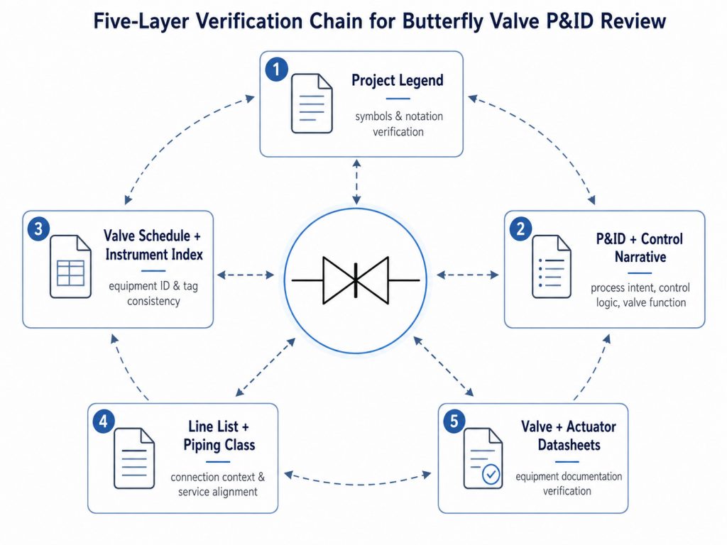
Verify a butterfly valve through a five-layer evidence chain before approving the drawing or valve list. Each layer answers a different question, so agreement across the set is more important than the detail shown on any one document.
- Legend and lead sheet: Confirm the body symbol, tag rules, actuator marks, line conventions, and state notation.
- P&ID and control narrative: Confirm the valve’s process duty, location, operating purpose, interlocks, normal state, and fail action.
- Valve schedule and instrument index: Confirm that the tag exists once, uses the same service description, and points to the correct specification.
- Line list and piping class: Confirm line size, design pressure and temperature, material class, flange standard, and any directional requirement.
- Valve and actuator datasheets plus approved drawing: Confirm construction, materials, dimensions, torque, actuator sizing, accessories, testing, and document deliverables.
When two layers conflict, do not let the more detailed-looking document win automatically. Record the discrepancy, identify the document owner, and obtain an approved revision or written clarification. That action creates a traceable decision instead of transferring an assumption into purchasing or fabrication.
Convert the Drawing Into an RFQ Release Gate
Release a butterfly valve RFQ only when the drawing intent has been converted into a complete and internally consistent requirement set. At minimum, the inquiry package should identify:
- Valve tag, service, quantity, and required function
- Nominal size, line class, pressure rating, and flange or connection standard
- Fluid, solids content if relevant, design pressure, design temperature, and differential pressure
- Body pattern, offset design if specified, preferred pressure direction, and installation constraints
- Body, disc, stem, seat, and liner materials
- Shutoff or leakage requirement and applicable valve or test standard
- Manual or powered operation, required torque basis, fail action, supply conditions, and control signal
- Solenoid, positioner, limit switches, position feedback, local controls, and enclosure requirements
- Inspection plan, material certificates, test reports, approved drawings, and other project documents
If the P&ID supplies only a tag and a symbol, the RFQ is not ready. Mark each missing field as a technical query, assign an owner, and hold the affected item until the valve schedule, piping class, process data, and control requirements agree.
Make the Symbol the Start of the Check
The safest reading of a butterfly valve P&ID symbol is that it identifies a valve type and process location, then directs you to the documents that define the real hardware and control behavior. Start with the disc cue, let the legend govern, separate tag and actuator information, distinguish normal, fail, and actual positions, and verify every procurement field outside the icon.
RUITO can review the P&ID, valve list, process conditions, piping standard, and actuator requirements as one package. To confirm a butterfly valve configuration or prepare a technical inquiry, send your project details to our engineering team.
FAQ
Is a Butterfly Valve Always Tagged BV on a P&ID?
No. BV may be used on some projects, but other tag systems identify the valve by function, actuator, or control loop. Use the project legend and valve schedule to confirm what the letters mean.
Are Normally Closed and Fail Closed the Same Condition?
No. Normally closed describes a defined normal process position, while fail closed describes the intended response to loss of a specified signal or energy source. The control narrative must define both conditions and the event that triggers the fail action.
What Should I Do if the Symbol and Valve Schedule Disagree?
Do not choose one by assumption. Log the discrepancy, place the affected drawing or RFQ item on hold, and obtain an approved correction from the responsible process, piping, or instrumentation owner.