
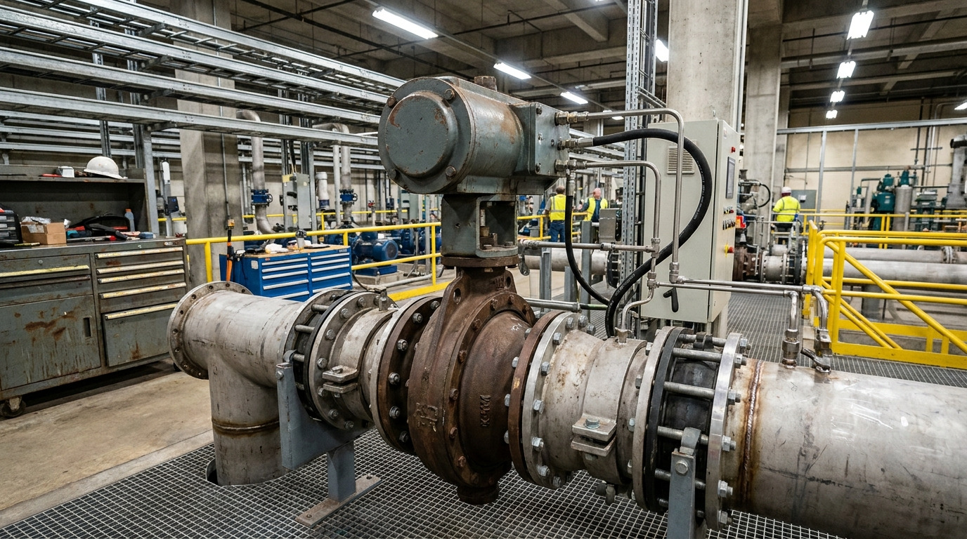
Actuated butterfly valves are quarter-turn devices that automate isolation or flow regulation in piping systems. A plant operator may need a large cooling-water valve closed within seconds, yet manual gearing can respond too slowly and expose people to a hazardous area. That delay can upset pressure, waste product, or damage downstream equipment. A correctly specified butterfly valve hydraulic actuator supplies dependable torque, controlled motion, and a defined response after power loss.
What Makes an Actuated Butterfly Valve Work?
A butterfly valve hydraulic actuator works by converting pressurized fluid into rotary torque that turns a central disc through roughly 90 degrees. Parallel alignment lets media pass, while perpendicular alignment shuts flow against a seat. Because that disc remains in the bore, its profile affects capacity, pressure loss, and control response. Your specification must treat valve, stem, coupling, and actuator as one torque-transmitting assembly.
How do the core parts share the load?
Here’s the practical point: each component must carry both static seating force and dynamic flow force without excess deflection.
- The body contains pressure and connects with adjacent pipework.
- The disc blocks or meters flow as its angle changes.
- The stem transfers actuator torque into disc rotation.
- The seat forms shutoff and sets friction demand.
| Part | Main duty | Selection check |
|---|---|---|
| Disc | Controls flow area | Profile and material |
| Stem | Transfers torque | Strength and fit |
| Seat | Provides shutoff | Media and temperature |
This comparison shows why a strong actuator cannot compensate for a weak mechanical interface. Key Takeaway: Specify every rotating and sealing part as a matched system, so commanded movement reaches the disc accurately.
Which Butterfly Valve Designs Fit Different Piping Systems?
A butterfly valve hydraulic actuator can operate concentric or eccentric valves, but service pressure, temperature, and shutoff demand determine which design fits. Concentric discs suit many water and low-pressure utility lines because a resilient seat provides economical sealing. Double-offset geometry reduces rubbing during travel, while triple-offset metal-seated construction serves hotter or more demanding duties. Your end connection must also match maintenance access and piping loads.
What should you compare before choosing a body style?
Here’s where choices narrow: compare piping layout with isolation policy before weighing purchase price.
- Wafer bodies save space between mating flanges.
- Lug bodies can support qualified dead-end service.
- Double-flanged bodies aid alignment on larger lines.
- Welded ends suit selected high-integrity applications.
| Design | Typical strength | Main check |
|---|---|---|
| Concentric | Simple resilient sealing | Seat compatibility |
| Double offset | Reduced seal wear | Pressure class |
| Triple offset | High-temperature shutoff | Required leakage class |
The pattern links geometry directly with service severity, rather than pipe diameter alone. Key Takeaway: Choose closure geometry and body ends before sizing actuation, since both decisions change torque and mounting requirements.
Which Actuation Method Best Matches Your Service?
A butterfly valve hydraulic actuator best matches high-torque, large-valve, or fast critical service where pressurized fluid is available. Manual operators fit infrequent local use, electric units suit clean remote positioning, and pneumatic units provide rapid cycling where plant air exists. You should compare energy supply, response time, fail action, and maintenance capability instead of selecting from torque alone.
Where does each power source perform best?
The deciding factor may surprise you: site infrastructure often removes an otherwise attractive option.
- Manual gearing favors small budgets and rare operation.
- Electric drives favor remote modulation and simple wiring.
- Pneumatic drives favor fast cycles and clean plant air.
- Hydraulic drives favor compact, high-force packages.
| Method | Relative torque | Best-fit duty |
|---|---|---|
| Manual | Low to medium | Local isolation |
| Electric | Medium | Remote positioning |
| Pneumatic | Medium to high | Rapid cycling |
| Hydraulic | High | Heavy-duty control |
This comparison favors available utility power that your maintenance team can support. Key Takeaway: Match actuation with real site resources and safety logic, then confirm torque across every operating condition.
How Does a Butterfly Valve Hydraulic Actuator Work?
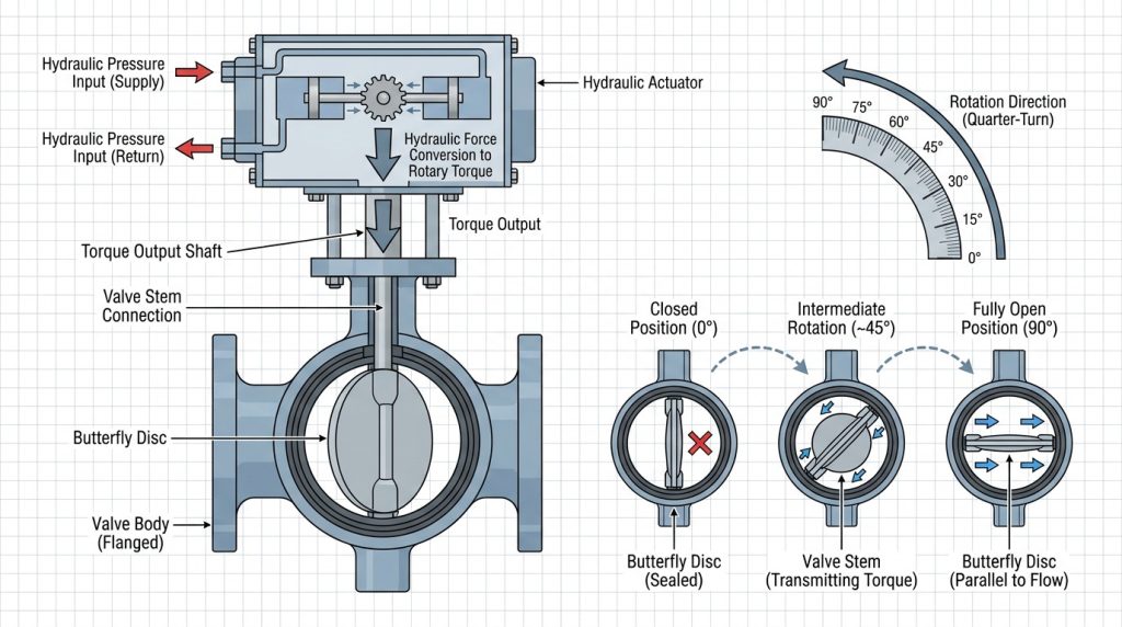
A butterfly valve hydraulic actuator directs pressurized oil or water against a piston or vane, creating rotation through a linkage or rack mechanism. Double-acting units use pressure for both directions, while spring-return units use stored spring energy for a defined fail position. A directional valve controls fluid routing, and position devices report actual travel. You gain high torque from a compact package, provided fluid cleanliness and seal condition remain controlled.
What happens during an open-close command?
Watch the sequence: a small control signal initiates a much larger mechanical response at the valve stem.
- A controller energizes a directional solenoid.
- Pressurized fluid enters one actuator chamber.
- Piston motion creates quarter-turn shaft rotation.
- Limit feedback confirms reached position.
| Stage | Input | Result |
|---|---|---|
| Command | Electrical signal | Flow path changes |
| Stroke | Fluid pressure | Stem rotates |
| Verification | Position feedback | Control state confirms |
The sequence reveals where pressure, contamination, or feedback faults can stop movement. Key Takeaway: Diagnose hydraulic supply, control valve, mechanical drive, and feedback in sequence when response becomes unreliable.
How Should You Calculate Required Actuator Torque?
A butterfly valve hydraulic actuator should be sized from seating, unseating, running, and dynamic torque at specified differential pressure. Add an approved service factor for temperature, deposits, aging seals, supply variation, and uncertainty in field conditions. Generic size charts cannot capture disc geometry or media effects. You also need torque in both directions because opening demand may differ sharply from closing demand.
Which torque inputs belong on your data sheet?
Here’s the catch: headline output torque means little unless it exceeds valve demand throughout travel.
- Record breakaway torque at opening.
- Check dynamic torque near peak flow loading.
- Confirm final seating torque without damaging seals.
- Apply minimum available hydraulic pressure.
| Torque term | When it occurs | Main driver |
|---|---|---|
| Unseating | Start of opening | Seat friction |
| Running | Mid travel | Bearing friction |
| Dynamic | Flowing travel | Velocity and disc angle |
| Seating | End of closing | Shutoff demand |
The highest demand may occur away from either travel limit, especially under strong flow. Key Takeaway: Size against a full torque curve at minimum supply pressure, not a single nominal number.
What Duty Cycle and Speed Does Your Process Need?
A butterfly valve hydraulic actuator needs a duty rating and stroke speed aligned with actual process frequency, control stability, and surge limits. Hydraulic packages can support frequent cycling, yet heat generation and seal wear still depend on load and fluid condition. Faster closure may protect a process, but it can also create water hammer or pressure shock. You should model line behavior before demanding the shortest stroke time.
How do you balance response against pipeline stress?
What matters next? Connect travel time with process dynamics rather than treating speed as an isolated purchase value.
- Count normal and emergency cycles separately.
- Set closing time against surge calculations.
- Check reservoir cooling for repeated strokes.
- Define modulation accuracy and allowable deadband.
| Duty | Preferred behavior | Risk to review |
|---|---|---|
| Emergency isolation | Fast defined closure | Pressure surge |
| Modulation | Smooth small steps | Hunting |
| Batch transfer | Repeatable timing | Heat buildup |
The comparison shows that fastest rarely means best for every pipeline. Key Takeaway: Specify duty and travel time from process studies, so valve response protects equipment without destabilizing flow.
How Do Media and Environment Affect Selection?
A butterfly valve hydraulic actuator must tolerate external surroundings while valve wetted parts tolerate process media. Corrosive vapor, salt spray, dust, washdown, extreme temperature, and hazardous-area rules can change housing, coating, seal, and control choices. Inside the pipe, slurry or crystallizing liquid can raise breakaway torque after idle periods. You should document both internal chemistry and external exposure on one selection sheet.
Which compatibility checks prevent early failure?
This is where details pay off: material names alone do not establish compatibility across temperature and concentration ranges.
- Verify body, disc, seat, stem, and packing materials.
- State media concentration and temperature limits.
- Define enclosure protection and corrosion coating.
- Identify hazardous-area certification needs.
| Exposure | Possible effect | Specification response |
|---|---|---|
| Abrasive solids | Seat and disc wear | Harder trim or lower velocity |
| Corrosive vapor | Housing attack | Coating and sealed enclosure |
| Cold climate | Viscosity increase | Suitable fluid and heating |
These exposure paths can raise torque or disable controls even when valve sizing looks correct. Key Takeaway: Treat internal media and external atmosphere as separate compatibility cases during technical review.
Which Fail-Safe Strategy Protects Your Process?
A butterfly valve hydraulic actuator protects your process only when its loss-of-power position matches hazard analysis. Fail-closed action stops feed or isolates inventory, fail-open action may preserve cooling, and fail-in-place action can stabilize selected control loops. Spring return, accumulators, or redundant hydraulic circuits provide stored energy. Your P&ID, cause-and-effect chart, and valve data sheet must show the same action.
How should you verify failure behavior?
Don’t stop at the label: a stated fail position needs enough stored torque and fluid volume under worst-case conditions.
- Simulate electrical and hydraulic supply loss.
- Measure travel time under differential pressure.
- Confirm end position through independent feedback.
- Test manual override and reset procedure.
| Fail action | Common purpose | Verification focus |
|---|---|---|
| Closed | Stop hazardous feed | Stored closing torque |
| Open | Maintain cooling flow | Stored opening force |
| In place | Hold process state | Leak-tight hydraulic lock |
The safest position depends on system consequences, not a universal convention. Key Takeaway: Define, document, and proof-test failure response under credible worst-case pressure and supply conditions.
How Do Mounting and Controls Affect Reliability?
A butterfly valve hydraulic actuator remains reliable when its mounting interface preserves alignment and its controls report true valve position. Matching an ISO 5211 flange pattern helps mechanical fit, but it does not prove adequate stem strength or torque capacity. Poor brackets and loose couplings add backlash, side load, and travel error. Control architecture must also match on-off, modulating, or emergency shutdown duty.
What belongs in an interface review?
Here’s a useful checkpoint: review mechanical, hydraulic, electrical, and logic interfaces in one session.
- Check flange pattern, stem form, and coupling depth.
- Verify bracket stiffness and alignment tolerance.
- Match signal type with positioner input.
- Set travel stops without overloading valve seats.
| Interface | Failure symptom | Review item |
|---|---|---|
| Coupling | Lost motion | Fit and key strength |
| Bracket | Binding | Alignment and stiffness |
| Feedback | False position | Calibration and mounting |
Most interface faults appear as erratic control rather than a clear component break. Key Takeaway: Validate physical fit and signal behavior together during factory acceptance and site commissioning.
What Do Cost and Maintenance Reveal About Value?
A butterfly valve hydraulic actuator provides value when lifecycle reliability offsets its hydraulic power unit, tubing, fluid care, and service labor. Purchase price alone hides downtime risk, spare-part availability, leakage control, and technician training. A maintainable package offers accessible seals, documented test points, and replaceable control modules. You should compare ownership cost across expected service life and production consequences.
Which maintenance evidence supports a sound purchase?
Now for the buying test: ask vendors for service records and inspection steps before approving technical bids.
- Request seal kits and recommended spare quantities.
- Review fluid cleanliness and sampling intervals.
- Confirm local technical support and lead times.
- Plan periodic stroke and fail-action tests.
| Cost area | Hidden exposure | Useful evidence |
|---|---|---|
| Energy | Continuous pump losses | Power-unit duty data |
| Maintenance | Unplanned seal work | Service schedule |
| Downtime | Lost production | Reliability history |
This lifecycle view places downtime and serviceability beside initial price. Key Takeaway: Buy documented reliability and maintainability, not actuator torque at the lowest quoted cost.
Ready to Specify a More Reliable Actuated Valve?
You now have a practical framework for valve geometry, actuation method, torque, speed, media compatibility, fail action, interfaces, and ownership cost. Share your line size, media, pressure, temperature, operating frequency, control signal, and required failure position when requesting a proposal. For application review and a matched valve-actuator package, contact us today. We believe dependable flow control begins with honest engineering choices that protect people, production, and every pipeline over its working life.
FAQ
Can I use hydraulic actuation for flow modulation?
Yes, provided your package includes a suitable positioner and stable hydraulic supply. Confirm control resolution, deadband, disc flow characteristic, and heat generation at expected cycle frequency.
What’s the best fail position for my butterfly valve?
There is no universal best position. Select fail-open, fail-closed, or fail-in-place from a documented hazard review covering pressure, inventory, cooling, and downstream consequences.
How do I know if my actuator has enough torque?
It has enough torque only when available output exceeds seating, unseating, running, and dynamic demand with an approved margin. Check this at minimum hydraulic pressure and worst service temperature.
Can I mount any hydraulic actuator on an ISO 5211 pad?
No, a matching pad confirms geometry rather than capacity. Verify flange size, coupling fit, stem strength, rotation direction, bracket stiffness, and actuator torque before assembly.
What’s the best maintenance check for reliable operation?
A scheduled partial or full stroke test gives strong evidence of movement, but it cannot replace inspection. Check fluid condition, leaks, fasteners, feedback calibration, hoses, seals, and fail-action performance.