
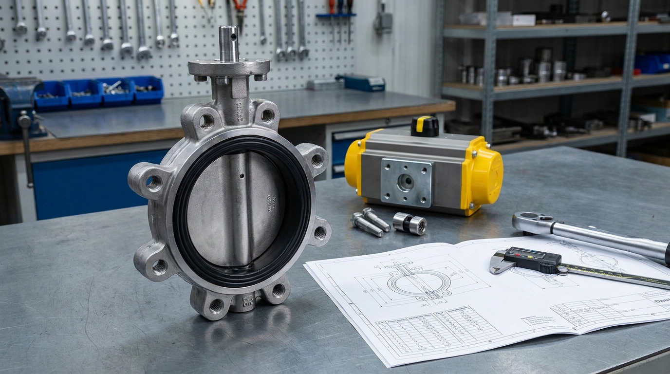
A butterfly valve parts diagram explains how the body, disc, stem, seat, seals, bearings, and actuator fit together to control flow with a quarter-turn motion. For a real project, you should read the diagram as a parts map first, then confirm dimensions, materials, pressure class, and actuator interface against the valve data sheet.
If you are checking a replacement valve, a spare seat, or an actuator package, the diagram helps you avoid a common mistake: matching the visible shape while missing the sealing design or mounting detail. When you compare a diagram with an actual butterfly valve specification, focus on the parts that affect fit, shutoff, torque, and connection to the pipeline.
How to Read a Butterfly Valve Parts Diagram
A butterfly valve parts diagram should be read from the pressure boundary inward: body and end connection first, then disc, stem, seat, seals, bearings, and operator. This order matters because the outside determines whether the valve fits the line, while the internal parts determine how it seals and operates.
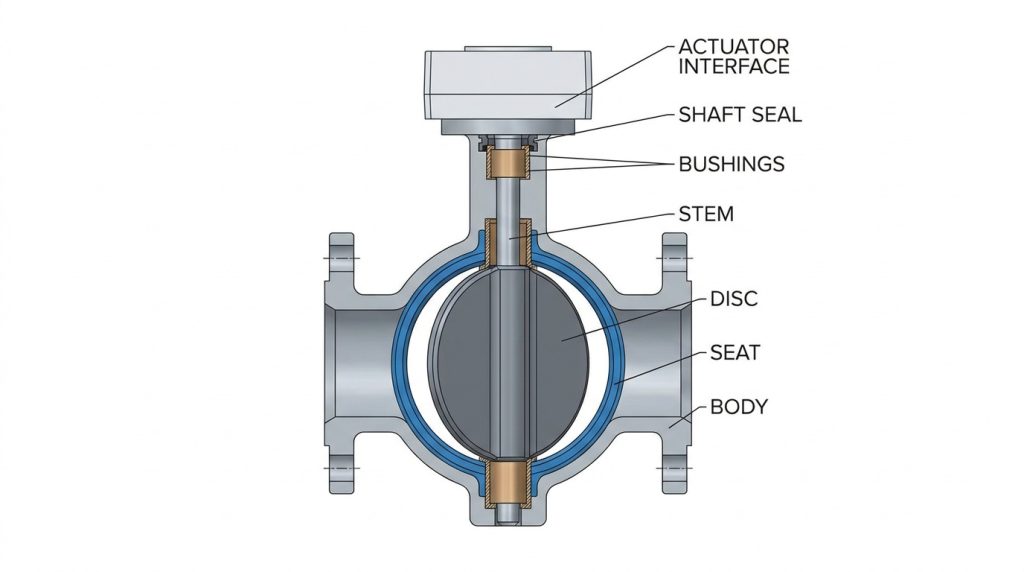
A good diagram is not just a picture of a valve. It should show enough callouts to let you identify replaceable parts, confirm the sealing arrangement, and understand how torque moves from the handle or actuator to the disc.
What should the callout list include?
The callout list should identify every part that affects assembly, sealing, or operation. If a diagram only labels “body, disc, stem, and actuator,” it is useful for basic learning but not enough for spare-part confirmation.
| Diagram callout | What it tells you | Why it matters |
|---|---|---|
| Body | Wafer, lug, double-flanged, or other body style | Determines flange connection, bolt path, and installation limits |
| Disc | Shape, material, and seating edge | Affects flow resistance, torque, and shutoff behavior |
| Stem or shaft | One-piece, two-piece, wetted, or non-wetted design | Controls torque transfer and media exposure |
| Seat or liner | Replaceable seat, bonded liner, cartridge seat, or metal seat | Determines sealing method and maintenance approach |
| Bushings and bearings | Stem support points | Help control shaft alignment and operating friction |
| Shaft seal or packing | Seal around the stem exit | Prevents external leakage at the top of the valve |
| Actuator interface | Handle, gearbox, pneumatic actuator, or electric actuator | Determines how the valve is operated and indicated |
The strongest clue in this table is the seat arrangement. In many butterfly valves, the seat is not just a small gasket; it may also act as the body liner and the flange sealing surface.
What does each drawing view reveal?
A section view shows the internal stack-up: disc edge, seat contact, shaft, bushings, and seal path. An exploded view helps you understand assembly order, especially when the valve has retaining rings, seat inserts, or separate shaft seals.
A side view is more useful for face-to-face dimension, flange contact, and actuator height. Do not treat one view as complete; you need at least the section view and outside dimensions before the diagram becomes useful for engineering review.
What Parts Should Appear in the Diagram
The diagram should show both the pressure-containing parts and the moving parts, because a butterfly valve fails to fit or seal when either group is misunderstood. The body, seat, disc, and stem are the core parts, but the small items around them often decide whether the valve can be assembled correctly.
When you review the diagram, separate “main structure” from “service parts.” Main structure includes the body and disc. Service parts may include the seat, stem seals, bushings, packing, retaining ring, bolts, keys, or position indicator.
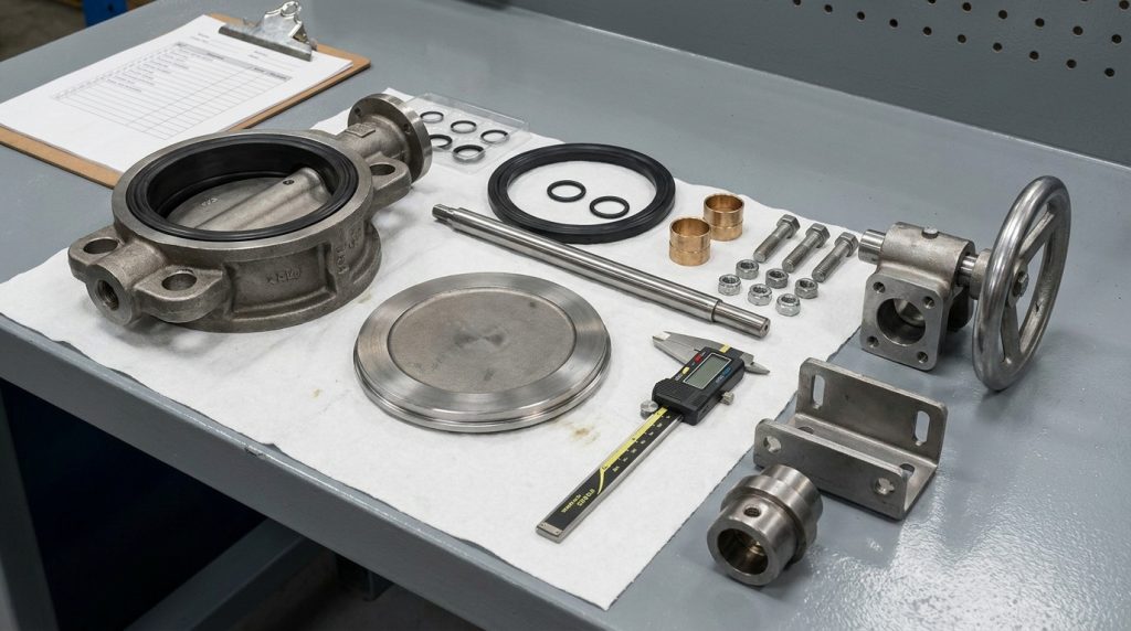
Body and end connection
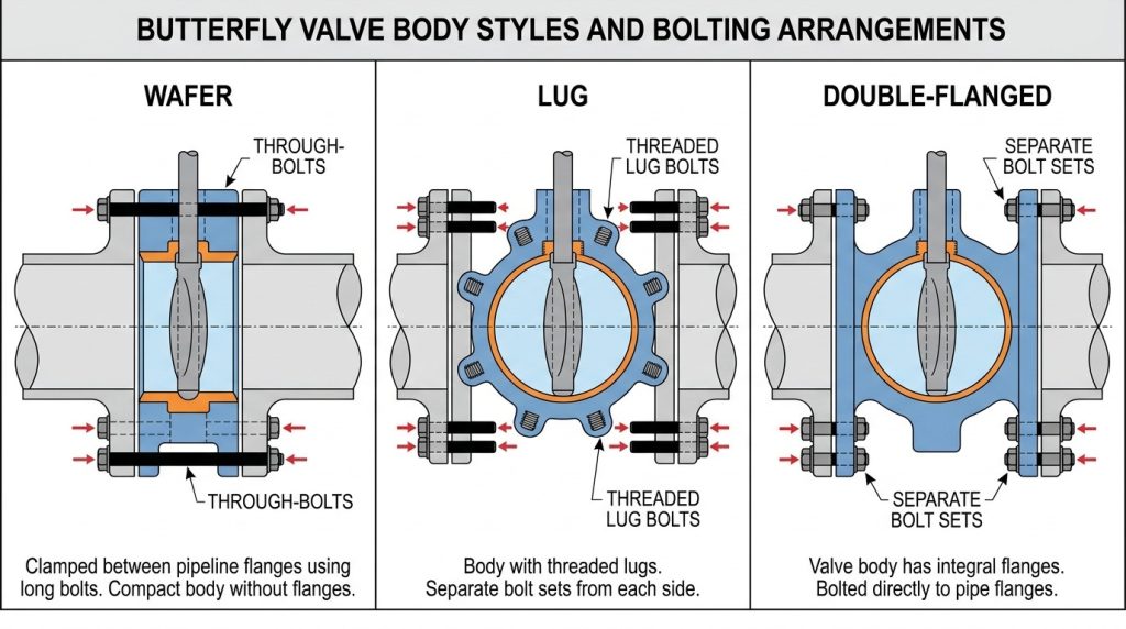
The body is the pressure boundary and the part that connects to the pipeline flanges. In a wafer valve, the body is clamped between flanges; in a lug valve, threaded lugs allow bolting from each side; in a double-flanged valve, the body has integral flanges.
A parts diagram should make the body style obvious. If it does not, the drawing is too general for ordering or installation decisions.
Disc, stem, seat, and seals
The disc is the rotating closure member. It stays in the flow path even when the valve is open, so the diagram should show disc thickness, seating edge, and shaft connection clearly enough to understand the flow obstruction.
The stem transfers torque from the operator to the disc. The seat creates shutoff at the disc edge, while shaft seals or packing control leakage where the stem exits the body. If you cannot see these parts in the diagram, you cannot reliably judge the sealing design.
Actuator, handle, gearbox, and position indicator
The topworks show how the valve is operated. Manual valves may use a lever for smaller sizes or a gearbox where torque is higher. Automated valves need a mounting pad, coupling, actuator, limit switch, solenoid, or position feedback depending on the control requirement.
A parts diagram may show the actuator as a simplified block, but the actuator interface should still be clear. For automated service, confirm the mounting standard, stem drive shape, torque requirement, fail position, and open-close indication before treating the diagram as complete.
Body Style Changes the Meaning of the Diagram
The same internal parts can mean different things when the body style changes, so always read the diagram together with the valve type. A wafer, lug, and double-flanged butterfly valve can all show a body, disc, stem, and seat, but they do not connect to the pipeline in the same way.
API Std 609, Tenth Edition, May 2026 covers butterfly valves in double-flanged, lug-, wafer-type, and butt-welding-end designs. That standard reference is useful because it reminds you that “butterfly valve” is not one physical layout.
Which body styles change the drawing?
A wafer valve drawing should make the clamped body and through-bolt path clear. A lug valve drawing should show threaded lug locations, because they affect bolting method and may affect dead-end service limits depending on the valve rating.
A double-flanged valve drawing should show flange thickness, bolt holes, and face-to-face length more explicitly. For large sizes or higher pressure classes, those external dimensions become as important as the internal sealing parts.
Which dimensions must not be assumed?
Do not assume face-to-face length, flange drilling, or bolt length from a simplified parts diagram. ASME B16.10-2022 covers face-to-face and end-to-end dimensions for valves to support installation interchangeability, but the actual drawing must still match the specified valve type, size, class, and end connection.
ASME B16.5-2025 covers pipe flanges and flanged fittings from NPS 1/2 through NPS 24 for several pressure classes, including Classes 150, 300, 400, 600, 900, and 1500, with Class 2500 covered through NPS 12. If your valve is for an ASME flanged line, the diagram should not be used alone; flange class, gasket surface, bolt pattern, and valve data sheet must agree. Proper centering also matters, so proper butterfly valve alignment should be treated as part of the fit review, not just an installation detail.
Seat and Disc Details Decide Shutoff Performance
The seat and disc contact area is the heart of the diagram because it shows how the valve seals. If you only check body style and actuator type, you may still choose the wrong valve for shutoff, temperature, media, or maintenance expectations.
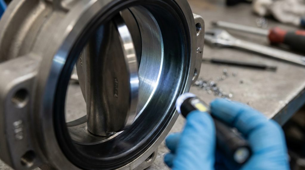
Soft-seated butterfly valves usually rely on elastomer or polymer contact between the seat and disc edge. Metal-seated designs use harder sealing surfaces and are often chosen for more severe temperature, pressure, or abrasive conditions, but their shutoff behavior and torque profile may differ from soft-seat valves.
Can the picture prove the sealing class?
No, the picture alone cannot prove leakage performance. A diagram can show the sealing concept, but leakage performance must be confirmed through the valve specification, test requirement, and manufacturer data.
For new industrial valves, test references such as API 598 or ISO 5208 may be specified to define inspection and pressure testing expectations. The diagram tells you where sealing occurs; the test standard and data sheet tell you what level of leakage performance is required.
Which seat details should you check?
Start by checking whether the seat is replaceable, bonded, molded into the liner, retained by a ring, or part of a cartridge-style assembly. This tells you whether maintenance is practical and what spare parts are needed.
Also check whether the seat seals only against the disc or also works as a flange seal. In many resilient-seated wafer valves, seat compression depends on correct flange contact and centering, so the body, seat, and installation condition cannot be judged separately.
Key Takeaway: If the seat detail is vague, the diagram is not enough for spare parts or shutoff decisions. Ask for the bill of materials, seat material, pressure-temperature rating, and applicable leakage test requirement.
Actuator and Stem Details Need Their Own Callouts
The actuator and stem details deserve separate attention because they control torque transmission, position indication, and automation compatibility. A valve can have the correct body and seat but still fail in service if the actuator interface or stem design is wrong.
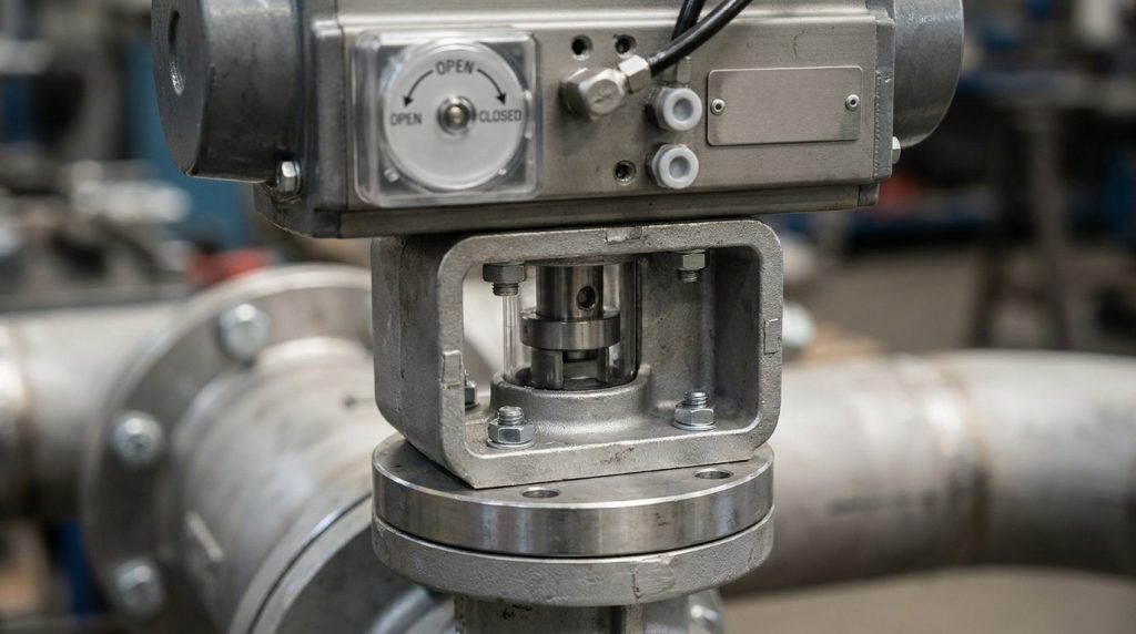
ISO 5211:2026 specifies requirements for part-turn actuator attachments to industrial valves, including flange dimensions, driving component dimensions, and reference torque values for interfaces and couplings. If the diagram shows an automated valve, the mounting interface should be checked against that requirement or the project-specified equivalent.
Why does 90-degree movement not mean linear flow?
A butterfly valve usually moves from closed to open through about 90 degrees, but percent open is not the same as percent flow. The disc remains in the flow path, and the effective flow area changes nonlinearly as the disc rotates.
This is why a diagram with 0-degree and 90-degree positions is useful for orientation but not enough for control judgment. If your next question is how disc angle affects capacity, pressure drop, or control response, review butterfly valve flow vs percent open before treating the valve as a linear throttling device.
What stem details affect operation?
Stem design affects strength, corrosion exposure, and maintenance. A one-piece shaft can give strong torque transfer, while a split-stem arrangement may reduce obstruction or simplify certain designs.
The drawing should show whether the stem is wetted by the media, isolated by the seat, or sealed by packing. For corrosive or abrasive service, that detail can influence stem material and long-term operating torque.
Diagram Review Checklist Before You Use the Drawing
Use the diagram as a verification tool, not as a substitute for the valve data sheet. Before ordering, replacing, or installing a butterfly valve, confirm the items that connect the picture to real project requirements.
| Item to verify | Standard or data basis | Practical check |
|---|---|---|
| Butterfly valve design type | API Std 609, Tenth Edition, May 2026 | Confirm wafer, lug, double-flanged, or butt-welding-end design |
| Face-to-face dimension | ASME B16.10-2022 where applicable | Match valve size, class, end connection, and replacement space |
| Flange connection | ASME B16.5-2025 for covered ASME flange sizes and classes | Confirm bolt pattern, pressure class, gasket face, and pipe flange match |
| Actuator mounting | ISO 5211:2026 or project-specified interface | Confirm top flange, drive coupling, torque, and actuator orientation |
| Seat and leakage expectation | API 598, ISO 5208, or project test requirement | Confirm seat type, test condition, and allowable leakage |
| Materials | Valve bill of materials and data sheet | Confirm body, disc, stem, seat, and seal compatibility with media |
This checklist is not meant to replace the project specification. It helps you catch the drawing items that most often cause mismatches: body style, flange fit, face-to-face length, actuator interface, and sealing requirement.
Common Misreads That Lead to Wrong Parts
Most diagram errors come from treating a simplified drawing as a manufacturing drawing. A general educational diagram can teach component names, but it may omit gasket details, shaft seals, retaining rings, actuator mounting dimensions, or exact material grades.
The safest way to read the drawing is to ask what decision it supports. If it supports basic learning, component labels may be enough. If it supports ordering or installation, you need the actual drawing number, revision, size, pressure class, bill of materials, and test requirement.
One more common misread is confusing a parts diagram with a P&ID or drawing symbol. A butterfly valve drawing symbol identifies the valve function in a process drawing, while a parts diagram explains the physical assembly. You need both in many projects, but they answer different questions.
Conclusion
A butterfly valve parts diagram helps you understand how the body, disc, stem, seat, seals, bearings, and actuator work together, but its real value comes from knowing what the drawing can and cannot prove. Use it to identify parts, check assembly logic, and spot the critical details that affect fit, shutoff, torque, and maintenance.
For a project review, compare the diagram with the valve data sheet, bill of materials, flange standard, face-to-face requirement, actuator interface, and test requirement. If you need help checking whether a valve drawing matches your media, pressure, temperature, connection, and actuator needs, contact us with the drawing or specification details for a practical review.
FAQ
Can I use a generic butterfly valve parts diagram to order spares?
Usually no. A generic diagram is useful for identifying part names, but spare parts require the exact valve size, model, seat design, material, and drawing revision. Seats, stems, bushings, and seals can vary even when the outside shape looks similar.
How do I know if the seat is replaceable?
Check whether the diagram shows a separate seat, retaining ring, cartridge, or liner. If the seat appears molded or bonded into the body, replacement may not be handled the same way as a loose resilient seat. Confirm this with the parts list before ordering spares.
What’s the best way to confirm actuator fit?
Confirm the actuator mounting pattern, stem drive shape, required torque, travel stops, and position indication. If ISO 5211:2026 or another mounting standard is specified, the valve top flange and actuator interface should match the project requirement.
Can I tell the flow direction from the parts diagram?
Sometimes, but not always. Many concentric resilient-seated butterfly valves are shown without a strict flow arrow, while some high-performance or offset designs may have a preferred pressure direction. Check the body marking, data sheet, and installation instruction before assuming bidirectional service.
How do I know if the diagram is detailed enough for installation?
It is detailed enough only if it includes the body style, face-to-face dimension, flange connection, disc orientation, seat arrangement, actuator clearance, and any installation notes that affect fit. If those items are missing, treat the diagram as educational and request the project drawing before installation.