
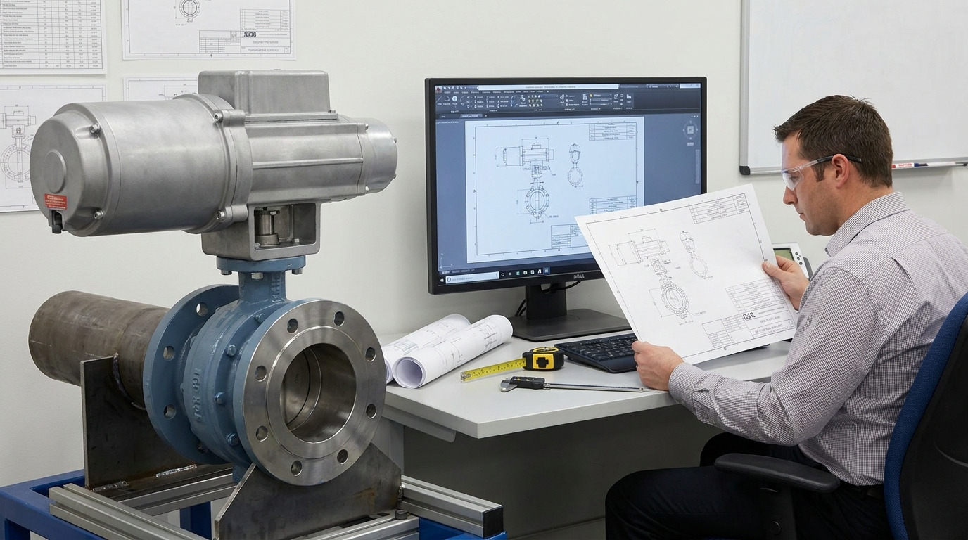
A butterfly valve drawing is useful only when you identify the drawing type and verify its symbols, dimensions, interfaces, configuration, and revision against the project documents. A P&ID symbol answers a different question from a dimensional drawing, and neither can replace a valve datasheet or an approved general arrangement drawing.
If you are selecting a valve, coordinating piping, or preparing an RFQ, the first task is therefore not to find any attractive outline. It is to find the controlled drawing that proves the exact valve will perform its intended function and physically fit the line.
A Butterfly Valve Drawing Can Mean Four Different Documents
A butterfly valve drawing may be a P&ID symbol, a general arrangement drawing, a sectional assembly, or an installation detail; each answers a different engineering question.
A butterfly valve is a quarter-turn rotary valve whose disc turns within the flow path to isolate or regulate flow. The drawing represents that function at a level of detail suited to process design, equipment coordination, construction, maintenance, or procurement.
Use this distinction before you review dimensions or send a file to procurement:
| Drawing type | What it should tell you | What it cannot prove alone |
|---|---|---|
| P&ID or schematic | Valve function, tag, location, actuator type, normal or fail state | Exact dimensions, materials, drilling, torque, or construction |
| General arrangement (GA) or dimensional drawing | Overall size, face-to-face length, connection details, actuator envelope, orientation | Internal part interfaces or full material verification |
| Sectional or exploded assembly | Body, disc, stem, seat, bearings, seals, fasteners, and part relationships | Installed clearance unless external dimensions are also shown |
| Installation or piping detail | Flanges, bolts, gaskets, pipe bore, disc clearance, access, and support conditions | Complete valve specification or internal materials |
The practical rule is simple: the P&ID defines what and where, the datasheet defines what to buy, the approved GA defines the physical interface, and the sectional drawing plus BOM defines the construction. Treating one file as all four is a common source of design-review and purchasing errors.
Read the P&ID Symbol as a Functional Reference
A P&ID symbol identifies function and control intent, not the valve’s full purchase specification. The symbol must be read with the project legend, tag, line class, valve schedule, actuator notation, and control narrative.
ISO 10628-2 defines graphical symbols for diagrams in the chemical and petrochemical industries, but an applicable standard does not make every project’s exact butterfly valve icon universal. Company CAD libraries and project legends may use different base shapes or abbreviations. The legend for the issued drawing set remains the working authority.
How to Draw a Butterfly Valve Symbol
Use the approved symbol library, place the base valve symbol in the process line, then add the information required by the project: tag number, manual or powered actuator, normal position, fail position, and relevant control connections. Do not add body style, seat material, or pressure class to the icon unless the drafting standard specifically requires it.
A base symbol can show that a butterfly valve is intended, but it usually cannot distinguish wafer, lug, or double-flanged construction. Before releasing a drawing, check these common butterfly valve P&ID review mistakes and confirm that the tag agrees with the valve schedule and datasheet.
Read the GA Drawing for Fit and Interface Control
A GA or dimensional drawing should prove that the exact valve package fits the piping and the surrounding space. It needs enough information for piping, structural, electrical, instrumentation, installation, and maintenance teams to coordinate their work.
Start with the title block. Confirm the manufacturer or drawing origin, model or configuration code, nominal size, pressure rating, end connection, actuator type, units, projection method, drawing number, revision, and approval status. A technically correct outline can still be the wrong file if it represents another size, pressure class, body pattern, or actuator.
Then check the interface dimensions:
- Face-to-face length and the standard or series used
- Flange outside diameter, bolt-circle diameter, hole count, hole diameter, and thread details where applicable
- Valve bore and the minimum adjacent pipe inside diameter
- Shaft centerline, mounting-pad pattern, actuator height, handwheel or lever sweep, and terminal-box orientation
- Overall mass and center of gravity when supports, lifting, or structural loads depend on them
ISO 5752:2021 specifies basic face-to-face and center-to-face series for butterfly and other metal valves in flanged pipe systems. For ASME projects, ASME B16.10-2022 addresses face-to-face and end-to-end dimensions to support interchangeability for a defined valve type, size, rating class, material, and end connection. A drawing should still state the applicable standard and the actual dimension; a standard name alone does not identify the selected series or configuration.
Use the Sectional Drawing to Verify Construction
A sectional or exploded drawing should show how the components interface and which parts the bill of materials identifies. It is the right document for checking construction logic, maintenance access, and whether the materials named in the datasheet are assigned to the correct components.
Trace the load and sealing path from the actuator or operator through the stem to the disc, seat, and body. Confirm the stem arrangement, retention method, bearings or bushings, seat retention, body seal, packing, fasteners, and any replaceable wear parts. For eccentric designs, the drawing should also make the offset arrangement and sealing contact understandable.
Do not infer metallurgy from color, shading, or a generic cross-section. Match every material callout to a BOM item, then compare the BOM with the approved datasheet and material requirements. A focused butterfly valve parts diagram can help you identify the interfaces to trace before maintenance or fit-up review.
Check the Installation Envelope, Not Just the Body Outline
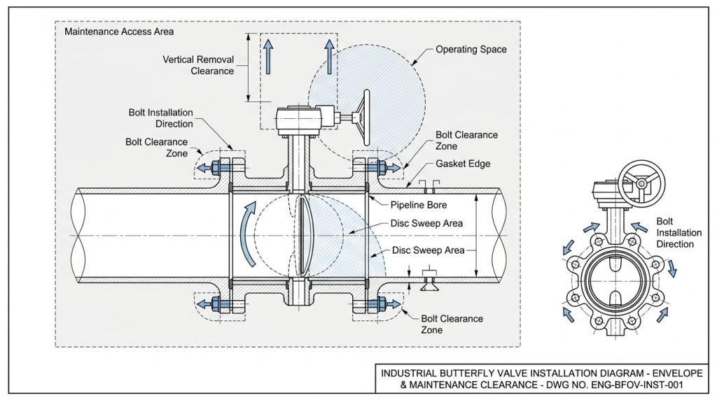
An installation review is incomplete until the drawing proves flange, bolt, pipe-bore, disc-swing, actuator, and maintenance clearances. The most serious clashes often sit outside the valve body’s visible outline.
On many butterfly valve designs, the disc projects beyond the body faces as it opens. Compare the manufacturer’s disc-swing envelope with the actual pipe inside diameter and with nearby reducers, check valves, internal weld beads, rubber linings, and other obstructions. Also confirm that the selected gasket does not intrude into the bore or interfere with the seat.
For wafer and lug bodies, review bolt length and insertion direction rather than copying a generic flange fastener list. Body thickness, tapped lug depth, flange thickness, gasket stack, washers, and available clearance all affect the usable fastener. A configuration-specific lug butterfly valve bolt chart is a better starting point than a chart that identifies only nominal pipe size.
Finally, model the operating and service space. Check lever or handwheel sweep, actuator removal height, access to fasteners, cable entry, solenoid and limit-switch access, lifting points, shaft orientation, and room to replace the seat or operator. A valve may fit between the flanges and still be impossible to operate or maintain.
Approve the Drawing With a Cross-Document Check
A drawing is ready for RFQ or approval only when its identity, configuration, interfaces, and revision status are unambiguous. Review it against the project documents rather than checking it in isolation.
The following matrix keeps each decision tied to its controlling evidence:
| Review question | Evidence on the drawing | Cross-check against |
|---|---|---|
| Does it perform the intended function? | Tag, actuator, normal and fail position | P&ID, valve schedule, control narrative |
| Is it the specified valve? | Size, rating, body pattern, materials, model code | Datasheet, piping class, project specification |
| Will it connect and fit? | Face-to-face, drilling, bore, overall envelope | Line layout, mating flanges, site or spool dimensions |
| Can it open and be maintained? | Disc swing, operator sweep, removal and access clearances | 3D model, adjacent equipment, maintenance plan |
| Is the file controlled? | Drawing number, revision, date, status, approvals | Document register, RFQ or PO, deviation list |
Record every mismatch as an open technical query or a documented deviation. Do not resolve a conflict by choosing whichever document is easiest to change. The project document hierarchy and written approvals should determine which requirement controls.
Request a Configuration-Specific Drawing Package
The most useful deliverable is a controlled package tied to the exact valve configuration, not a generic marketing outline. State the required file formats and review stage in the RFQ so the supplier knows whether you need a reference PDF, editable 2D CAD, a 3D coordination model, or an approval drawing.
For its industrial butterfly valve configurations, RUITO accepts PDF/DWG inputs and can prepare 3D models, technical drawings, and BOMs for review. The same first-party page states that custom orders include engineering drawings and material test reports, while dimensional inspection covers the bore, face-to-face length, flange drilling, and shaft concentricity. It also describes drawing archiving and revision control for repeat orders.
When requesting a drawing pack, provide the valve tag, service, size, design pressure and temperature, connection standard, body pattern, materials, actuation, fail position, accessories, pipe inside diameter, available envelope, documentation standard, and required approval date. Ask the supplier to list assumptions and deviations on the drawing or in a linked schedule. That turns the drawing into a controlled interface document rather than a sales illustration.
Put the Right Drawing Under Control
A reliable butterfly valve drawing connects process intent, purchase specification, physical fit, construction, and document status without contradiction. Start with the drawing type, follow the tag across the P&ID, schedule, datasheet, GA, sectional drawing, and BOM, then verify installation clearances and revision status before approval.
If you need a dimensional drawing, a configuration review, or a drawing package for an RFQ, send your project drawing and service conditions to RUITO. We can help confirm which valve configuration and document set should move forward for approval.
FAQ
Which file format should I request for a butterfly valve drawing?
Request PDF for the controlled review record, DWG or DXF when your team must edit or coordinate 2D geometry, and STEP or another agreed neutral format for 3D clash checking. State the required software version, units, coordinate system, and whether the file is reference-only or approved for design.
Should the actuator appear on the valve GA drawing?
Yes, if the valve and actuator will be purchased or installed as one package. The GA should show the complete envelope, mounting orientation, handwheel or lever sweep, terminal-box or accessory positions, removal clearance, and total mass when these affect coordination.
Can one generic drawing cover every butterfly valve size?
No, not for final design or procurement. Size, pressure rating, body pattern, flange standard, disc envelope, stem, operator, and accessory arrangement can change the critical dimensions, so the approved drawing must identify the exact configuration.