
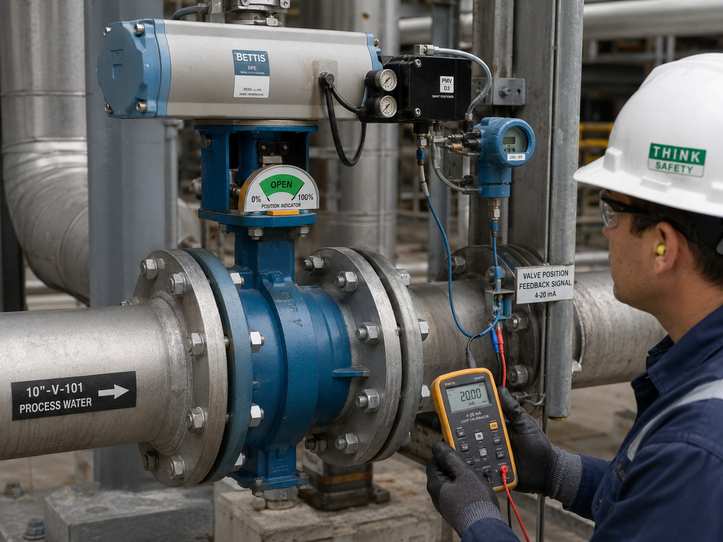
To verify the butterfly valve open position, confirm that the disc has completed its quarter-turn into alignment with the flow path, then match that mechanical position to the correct handle, gearbox, or actuator indication. A lever parallel to the pipe is the familiar quick check, but it is not enough when an operator has been removed, an indicator is loose, or a remote system shows only the command it sent. The reliable approach is to identify the valve’s operating mechanism, use direct position evidence first, and add an independent confirmation when the valve affects isolation or process safety.
What the Fully Open Position Actually Means
A fully open butterfly valve has its disc face parallel to the pipe centerline and the intended flow path. Viewed from upstream, the disc presents its edge to the flow, while the shaft axis still runs across the bore. Keeping the disc face, disc edge, and shaft axis separate prevents a common direction error.
For a conventional quarter-turn valve, the disc travels about 90° between closed and fully open. In the closed position, the disc face lies across the bore. In the open position, the disc face turns into the flow direction. A direct lever normally follows the disc plane, so it lies parallel to the pipe when open and perpendicular when closed. The handle may point upstream or downstream; either direction can indicate open because alignment, not the pointing direction, is what matters.
Fully open also means the valve has reached its designed open travel stop, not that the pipe has become completely unobstructed. The disc edge and shaft remain in the bore, so the valve still creates some pressure loss. If an actuator display uses 0% and 100%, treat those values as travel indications and verify how the manufacturer has assigned them to the closed and open endpoints.
Match the Position Check to the Operator
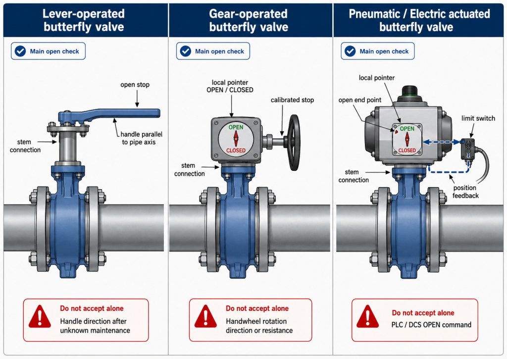
The correct external check depends on whether the butterfly valve uses a lever, gearbox, or powered actuator. Do not apply the lever rule to every operator type.
Lever-operated valves
For a lever-operated valve, release the latch and move the handle toward the marked open end of the locking plate. Fully open is normally the end notch with the handle parallel to the pipe. Check that the handle hub is tight on the stem and that the locking plate has not shifted; a parallel handle cannot prove disc position if the coupling is loose or was reassembled incorrectly.
Notched plates are useful for repeatable intermediate positions, but their marks indicate travel, not measured flow. Different butterfly valve handle options also change how the operator locks, reaches, and displays position.
Gear-operated valves
For a gear-operated valve, use the local OPEN/CLOSED pointer and its calibrated travel stop. Turn the handwheel only in the direction shown on the gearbox or in the operating manual, and stop when normal endpoint resistance is reached. Do not assume every gearbox opens counterclockwise, and do not force the handwheel to make the pointer reach its mark.
If the pointer stops short, continues past the mark, or does not move with the handwheel, treat the position as unconfirmed. The operator ratio, output torque, travel stops, and indicator setup should all be checked when selecting or commissioning a butterfly valve gearbox.
Pneumatic and electric actuators
For an actuated valve, compare the local mechanical pointer with actual endpoint feedback. An OPEN command proves only that the controller requested movement. An open limit switch proves that the actuator reached its calibrated switch point, while a continuous transmitter shows the measured travel value. Neither proves actual disc position if the stem coupling has slipped, so coupling integrity and endpoint calibration remain part of commissioning.
On spring-return pneumatic actuators, also distinguish the current position from the fail position. “Fail open” describes what the assembly is intended to do after loss of its energy source; it does not by itself confirm that the valve is open now.
Apply a Two-Signal Verification Rule
Use one direct position signal plus a second, independent signal whenever an incorrect indication could cause a process upset or defeat isolation. At least one signal should be tied to mechanical travel; pressure, temperature, or flow response alone is only supporting evidence.
The following table separates useful evidence from shortcuts that are easy to misread.
| Situation | Primary position evidence | Independent confirmation | Do not accept alone |
|---|---|---|---|
| Routine lever valve | Handle at the open stop with a sound stem connection | Documented shaft reference or an authorized controlled-stroke check | Handle direction after unknown maintenance |
| Gear-operated valve | Calibrated local pointer at the open stop | Verified full-travel record or documented stem reference | Handwheel direction or resistance |
| Automated valve | Local pointer at the open endpoint | Open limit switch or calibrated transmitter feedback | PLC/DCS OPEN command |
| After operator removal | Recalibrated mechanical endpoints | Switch and indication test at both endpoints | Repainted arrows or an old decal |
| Isolation-critical duty | Approved position proof in the operating procedure | Required isolation verification for the system | Any single visual cue |
The strongest combination for an automated valve is usually local mechanical indication plus independent electrical feedback. A process trend can corroborate the result, but it cannot resolve every case: zero flow may mean the pump is off, downstream pressure may come through a bypass, and trapped pressure can remain behind a closed valve.
Resolve Conflicting Indications Without Guessing
When the indicators disagree, mark the valve position as unknown and stop using it as a confirmed isolation boundary. The correct response is a controlled verification sequence, not additional force on the operator.
- Confirm the valve tag, operator type, and open/closed convention from the approved drawing or operating manual.
- Inspect visible parts without dismantling them. Look for a loose handle hub, damaged pointer, shifted scale, loose fasteners, or a coupling that moves independently of the stem.
- If operation is authorized, perform a controlled stroke while one person observes the local pointer and another checks the limit switches or transmitter. Stop for abnormal torque, noise, incomplete travel, or inconsistent feedback.
- Compare the result with available process data, but use pressure or flow only as corroboration.
- If the conflict remains, isolate the equipment, remove stored pressure and actuator energy, and apply the site energy-control procedure before loosening a gearbox, actuator, coupling, or valve component.
For US workplaces, OSHA’s control of hazardous energy guidance explains why servicing work must be protected against unexpected energization and hazardous energy release. A closed upstream valve is not, by itself, proof that the section you are touching is depressurized.
Separate Disc Travel from Flow Percentage
A butterfly valve at 45° is approximately halfway through its angular travel, but it is not necessarily passing 50% of the full-open flow. Capacity changes with disc angle, valve design, system pressure drop, and the rest of the piping resistance.
This distinction matters when a notched lever, actuator display, or control system reports percent open. Use the valve-specific Cv data and the system operating points to translate travel into capacity. A butterfly valve flow characteristic is the proper basis for that judgment, not a linear assumption from handle angle.
For on/off service, full open means the calibrated open endpoint has been reached. For throttling service, the intended operating position may be below full travel, but it should still be identified as a controlled intermediate position rather than “open” without qualification.
Specify Position Evidence Before Commissioning
A position-critical butterfly valve should be specified with the evidence needed to prove its travel in the installed system. Define that requirement before ordering the operator, not after startup exposes an ambiguous indication.
Include these items in the valve and actuator data sheet:
- A visible local indicator keyed to the actual disc orientation
- Adjustable, lockable mechanical stops for the closed and open endpoints
- Open and closed limit switches, or continuous position feedback where remote proof is required
- A clearly defined fail position and energy-loss response
- A drawing that states the angular convention, indicator orientation, wiring, and terminal assignments
- A commissioning test that records local indication, feedback, and process response at both endpoints
RUITO’s industrial butterfly valve range includes manual gear, electric, and pneumatic actuation options. Its published assembly audit checks operating torque at 0°, 45°, and 90° and records the result in a torque test log. For a position-critical package, supplement that production record with the actuator’s calibrated endpoint and feedback checks after final assembly and again during site commissioning.
Make Position Proof Part of the Operating Method
Reliable position confirmation comes from matching disc geometry to the operator and verifying the result with evidence appropriate to the risk. A parallel lever is usually enough for a routine, untouched manual valve; an automated or isolation-critical valve needs calibrated local indication, independent feedback, and a defined response when the two disagree.
RUITO can review the valve type, operator, feedback requirement, fail action, and documentation needed for your project. To confirm a new package or resolve an unclear specification, contact our valve engineering team.
FAQ
Can an open butterfly valve handle point upstream or downstream?
Yes. On a correctly assembled direct-lever valve, the handle can point in either direction along the pipe when open. What matters is that it is parallel to the pipe axis and correctly coupled to the disc.
Is 45° open equal to 50% flow?
No. It represents roughly 50% of the valve’s angular travel, not half of the flow capacity. Actual flow depends on the valve-specific characteristic and the system pressure drop.
What is the difference between fail-open and fully open?
Fail-open is a safety action specified for an actuated valve after loss of air, electrical power, or another energy source. Fully open is the valve’s present mechanical endpoint, which still needs position indication or feedback to confirm it.
Why can flow remain when the indicator says closed?
Flow can remain because the indicator is miscalibrated, the coupling has slipped, the seat leaks, or another flow path such as a bypass is open. Treat the position as unconfirmed and follow the system’s isolation and verification procedure before maintenance.