
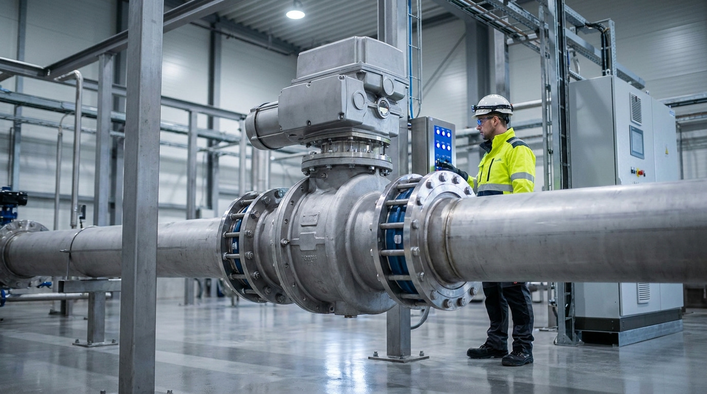
Modulating fluid involves specific geometric behaviors defining how rotary discs manage pressure drops. You might encounter situations where adjusting a pipeline creates unexpected pipe vibrations. Left unchecked, such turbulence damages infrastructure rapidly, halting industrial operations. By understanding butterfly valve flow characteristics, operators can specify throttling configurations accurately, preventing mechanical failures entirely. Mastering these profiles ensures your process loops remain stable.
What Are Butterfly Valve Flow Characteristics?
These profiles describe how media volume shifts when discs rotate open. Analyzing butterfly valve flow characteristics reveals an equal percentage inherent curve for most models. Such profiles mean equal increments of disc rotation yield uniform percentage changes in volume. Engineers rely on this geometric relationship for critical process modulation.
Defining Equal Percentage Curves
Consider this fact: equal percentage designs excel during varying pressure drop scenarios. They deliver precise throttling at minor angles.
- Minor rotation creates small volume shifts.
- Mid-range angles provide steady adjustments.
- Wide angles allow massive output surges.
Why Inherent Curves Matter
Ready for the good part? Knowing inherent geometry prevents poor actuator sizing during plant design phases. You can avoid specifying oversized components.
Key Takeaway: Recognizing equal percentage geometries helps you configure process loops efficiently without wasting energy.
| Characteristic Type | Opening Range | Flow Change Profile | Best Application Suitability |
|---|---|---|---|
| Equal Percentage | 30° – 70° | Exponential volume shifts | Varying pressure pipelines |
| Linear | 0° – 90° | Proportional adjustments | Constant pressure setups |
| Quick Opening | 0° – 30° | Rapid maximum volume | Emergency shutoff lines |
Evaluating inherent profiles ensures accurate valve selection for dynamic industrial environments.
Why 30-70° For Butterfly Valve Flow Characteristics?
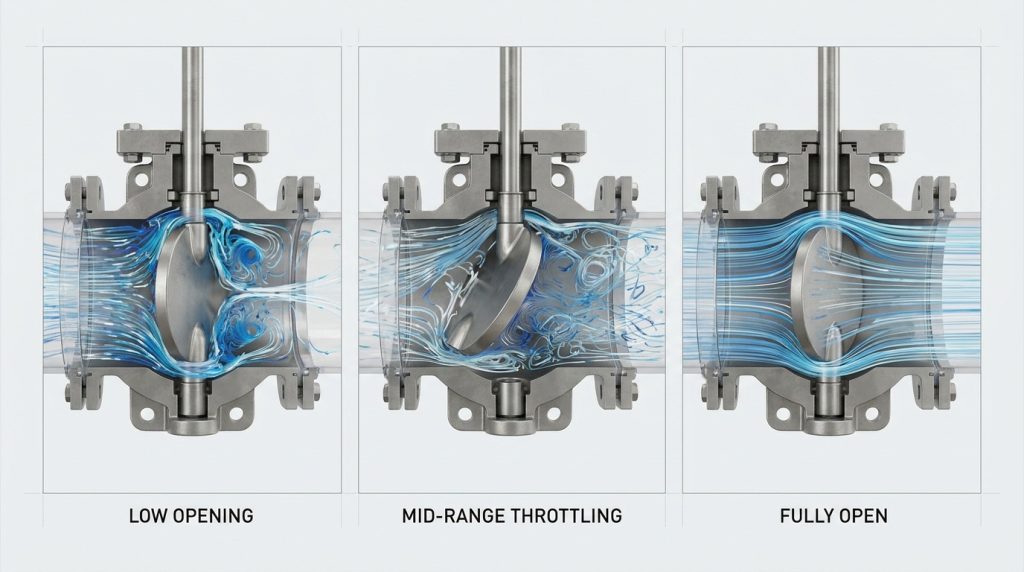
Throttling remains stable only within this specific angular window. Leaving this ideal zone degrades butterfly valve flow characteristics, causing severe equipment damage over time. You must restrict continuous modulation within these geometric boundaries. Operating outside these angles risks structural integrity.
Avoiding Low Opening Risks
What’s the real story? Operating below thirty degrees creates dangerously narrow gaps. Fluids jet rapidly through these spaces.
- Narrow openings induce destructive cavitation.
- High velocity causes localized seat erosion.
- Micro-bubbles implode, destroying metal surfaces.
High Angle Flatline Issues
Here’s the kicker… pushing past seventy degrees flattens output responses drastically. Moving discs further yields negligible volume improvements.
Key Takeaway: Confining continuous modulation between thirty and seventy degrees guarantees prolonged component lifespan.
| Disc Angle | Flow Behavior | Potential Equipment Risk | Recommended Action |
|---|---|---|---|
| 0° – 30° | High velocity jetting | Seat erosion, cavitation | Avoid continuous throttling |
| 30° – 70° | Proportional control | Minimal wear, stable | Ideal control range |
| 70° – 90° | Negligible change | Loss of control | Use for on/off only |
Maintaining operations within optimal angles prevents premature structural degradation.
How Does Cv Alter Butterfly Valve Flow Characteristics?
Cv values indicate gallons flowing per minute given one psi drop. Mapping butterfly valve flow characteristics against Cv charts dictates exact pipe sizing. Higher capacities at full open allow massive fluid transfers without bottlenecking. Matching Cv metrics against system demands prevents unwanted starvation.
Reading Cv Flow Curves
Look closely at this: graphical charts plot capacities against percentage rotation accurately. Ten percent yields minor capacities but dangerous velocities.
- Midpoint rotations achieve forty percent capacity.
- Full rotation minimizes turbulence completely.
- Peak capacities suit unhindered pipeline transfers.
Matching Cv With Systems
You might be wondering: how can engineers utilize these charts effectively? You must calculate peak demands accurately before consulting catalog graphs.
Key Takeaway: Calculating system capacities against manufacturer Cv charts guarantees seamless pipeline integration.
| Valve Position | Typical Cv Percentage | Turbulence Level | System Impact |
|---|---|---|---|
| 20% Open | 5% – 10% | Severe | High stress |
| 50% Open | 30% – 40% | Moderate | Stable throttling |
| 100% Open | 100% | Minimal | Maximum transfer |
Aligning required volumes with listed Cv metrics eliminates operational bottlenecks.
Globe Vs Butterfly Valve Flow Characteristics?
Globe types feature linear profiles while rotary disks offer equal percentages. Comparing globe models and butterfly valve flow characteristics highlights distinct engineering compromises regarding pipe diameters. Rotary designs save space but require stricter throttling boundaries. Globe structures handle severe drops easily.
Comparing Linear And Rotary
This is where it gets interesting… globe designs handle extreme throttling across full strokes smoothly. Rotary variants become unstable at narrow angles.
- Rotary types cost less on large pipes.
- Linear types resist high pressure drops.
- Discs need careful tuning against hunting.
Space And Cost Factors
But wait, there’s more: compact rotary styles save immense installation costs. You simply cannot ignore weight savings on overhead piping.
Key Takeaway: Choosing rotary styles saves money but demands rigorous control logic programming.
| Feature Comparison | Globe Model | Rotary Disc Model | Project Impact |
|---|---|---|---|
| Throttling Range | 10% – 90% | 30% – 70% | Affects loop tuning |
| Initial Cost | High | Low | Determines budget |
| Pressure Drop | High | Low | Impacts pump power |
Selecting compact designs reduces infrastructure costs significantly when sized correctly.
What Field Factors Change Butterfly Valve Flow Characteristics?
Installed dynamics often alter theoretical laboratory metrics completely. Changing friction forces morph butterfly valve flow characteristics from equal percentage into pseudo-linear shapes. You must account for adjoining pipe resistance during final calculations. Dynamic resistance reshapes expected performance curves.
Recognizing Installed Characteristics
Truth be told: theoretical curves warp once installed into complex networks. Surrounding pipe friction shifts inherent profiles drastically.
- Viscous fluids deform catalog curves.
- Upstream bends alter fluid entry vectors.
- Pressure drops shift across varying flowrates.
Dealing With Fluid Viscosity
Let’s dive deeper: thick fluids demand larger openings for identical output volumes. You should analyze media density closely.
Key Takeaway: Adjusting theoretical calculations for field realities ensures accurate process modulation.
| Field Variable | Effect on Flow Curve | Required Adjustment | Monitoring Method |
|---|---|---|---|
| Pipe Friction | Shifts curve towards linear | Recalculate installed Cv | Pressure sensors |
| Fluid Viscosity | Requires wider disc angles | Upsize valve slightly | Flow meters |
| Upstream Bends | Induces turbulent noise | Add straight pipe runs | Vibration testing |
Compensating for dynamic field variables prevents post-installation commissioning headaches.
How Does Cavitation Affect Butterfly Valve Flow Characteristics?
Micro-bubble implosions destroy metal components rapidly during narrow rotations. Unchecked cavitation ruins butterfly valve flow characteristics by altering internal surface geometries permanently. You must maintain adequate backpressure avoiding vapor thresholds entirely. Destructive vibrations signal impending mechanical failure.
Understanding Vapor Pressure
Listen to this: sudden pressure drops below liquid vapor limits trigger bubble formations instantly. Imploding vapor creates shockwaves against metal seats.
- Narrow gaps accelerate fluid dangerously.
- Shockwaves erode stainless steel discs.
- Constant vibration loosens stem connections.
Preventing Bubble Implosions
Want a quick fix? Keeping operations above thirty degrees mitigates low-angle velocity spikes. You can also install anti-cavitation trim.
Key Takeaway: Monitoring pressure differentials prevents cavitating conditions, safeguarding expensive pipeline assets.
| Cavitation Stage | Physical Symptom | Damage Level | Preventive Measure |
|---|---|---|---|
| Incipient | Light popping noise | Minimal | Increase backpressure |
| Moderate | Gravel-like rattling | Pitting on disc | Restrict angle limits |
| Severe | Violent pipe vibration | Material failure | Install specialized trim |
Implementing strict angle boundaries eliminates destructive bubble implosions effectively.
Can Piping Alter Butterfly Valve Flow Characteristics?
Upstream turbulence dramatically distorts fluid entry angles across internal disks. Close proximity elbows ruin butterfly valve flow characteristics by creating uneven velocity profiles. You need adequate straight pipe lengths before throttling zones. Symmetrical flow ensures predictable control responses.
Managing Asymmetrical Profiles
You heard it right: placing elbows too close causes disks to vibrate violently. Uneven forces twist stems out of alignment.
- Install six straight diameters upstream.
- Keep downstream sections clear.
- Symmetrical entry stabilizes control loops.
Solving Installation Errors
Here is a secret: correcting poor piping layouts solves erratic modulation instantly. You must review isometric drawings diligently.
Key Takeaway: Designing sufficient straight runs before process components guarantees accurate performance metrics.
| Piping Condition | Flow Profile | Component Stress Level | Recommended Action |
|---|---|---|---|
| Straight Pipe | Symmetrical | Low | Maintain design |
| Close Elbow | Asymmetrical | High | Relocate component |
| Swirling Fluid | Unpredictable | Extreme | Install flow straighteners |
Enforcing strict piping geometry rules stabilizes dynamic process control loops.
How Do Actuators Impact Butterfly Valve Flow Characteristics?
Pneumatic drivers must match rotational torque demands perfectly for precise modulation. Weak actuators fail against dynamic butterfly valve flow characteristics during high velocity surges. You need strong positioners handling aerodynamic disk pull accurately. Mismatched torque ratings cause severe hunting.
Sizing Pneumatic Drivers
Fact check: fluid passing moving discs creates aerodynamic torque pulling them closed. Actuators require enough power resisting these dynamic forces.
- Hydrodynamic pull peaks near seventy degrees.
- Weak springs cause sudden slamming.
- Digital positioners stabilize output signals.
Eliminating Control Hunting
Want better results? Specifying high-resolution positioners stops endless actuator oscillation. You achieve pinpoint rotational accuracy easily.
Key Takeaway: Pairing robust actuators with high-resolution positioners ensures smooth process modulation.
| Actuator Type | Control Precision | Torque Capacity | Best Use Case |
|---|---|---|---|
| Basic Pneumatic | Low | Medium | Standard on/off |
| Smart Positioner | High | High | Modulating control |
| Electric Motor | Very High | Very High | Remote precision tasks |
Deploying smart positioners mitigates aerodynamic torque fluctuations seamlessly.
Does Viscosity Change Butterfly Valve Flow Characteristics?
Thick syrups behave entirely differently than thin water streams inside pipes. High viscosity shifts butterfly valve flow characteristics away from standard laboratory test data. You must apply correction factors when sizing components for viscous media. Sluggish liquids require larger internal clearances.
Applying Correction Factors
Keep this in mind: viscous fluids increase friction coefficients dramatically across disk surfaces. Catalog Cv charts overestimate actual field capacities.
- Calculate Reynolds numbers carefully.
- Apply manufacturer viscosity corrections.
- Expect flatter inherent profiles.
Handling Slurries
Consider this workaround: handling abrasive slurries requires specially coated disks. You cannot treat dense mixtures like clean water.
Key Takeaway: Correcting catalog data for viscous fluids prevents under-sizing critical pipeline hardware.
| Fluid Viscosity | Flow Behavior | Sizing Impact | Hardware Recommendation |
|---|---|---|---|
| Low (Water) | Predictable, fast | Use catalog Cv | Standard disc |
| Medium (Oil) | Sluggish | Apply minor correction | Undercut disc |
| High (Slurry) | High friction | Apply major correction | Coated wear-resistant disc |
Factoring viscosity shifts into calculations guarantees adequate output during production runs.
How To Optimize Butterfly Valve Flow Characteristics?
Fine-tuning control loops aligns digital commands with mechanical realities seamlessly. Optimizing butterfly valve flow characteristics requires analyzing actual pressure drops during live production. You can calibrate smart positioners matching exact pipeline demands. Regular maintenance preserves original geometric tolerances.
Calibrating Smart Systems
Here’s a pro tip: modern digital positioners allow custom characterization curves via software. You easily reshape output behaviors digitally.
- Map custom points via software.
- Smooth out non-linear zones.
- Monitor diagnostic health remotely.
Routine Maintenance Checks
Don’t ignore this: worn seating surfaces alter inherent profiles drastically. You should inspect elastomer liners annually.
Key Takeaway: Combining digital characterization with routine physical inspections maximizes long-term throttling precision.
| Optimization Method | Implementation Difficulty | Performance Gain | Frequency |
|---|---|---|---|
| Digital Custom Curve | Low | High | Initial commissioning |
| Seat Inspection | Medium | Medium | Annually |
| Loop Tuning | High | Very High | After major process changes |
Leveraging digital characterization tools transforms erratic pipelines into highly efficient networks.
Selecting proper hardware requires understanding dynamic fluid behaviors completely. By mastering geometric profiles and optimal modulation zones, you prevent premature mechanical failures while saving infrastructure costs. Ruitoflow provides custom fluid control solutions engineered specifically for demanding industrial applications. When you need verifiable certificates and seamless site integration, contact us today for reliable hardware. We design robust components ensuring your global process lines remain continuously efficient.
FAQ
Q1: Can I use these designs for continuous throttling below 30 degrees?
No, throttling below thirty degrees causes destructive cavitation. The narrow gap accelerates fluid velocities dangerously, eroding internal metal components rapidly.
Q2: What’s the best way to determine the correct Cv value?
Calculate your maximum system demand first. Match that peak volume against manufacturer Cv charts targeting a sixty percent rotation for optimal control.
Q3: How do I know if my pipeline layout affects control stability?
Observe actuator behavior for erratic hunting or listen for vibration. Placing elbows too close disrupts fluid entry angles, creating turbulent asymmetrical forces.
Q4: Can I change an equal percentage profile into a linear one?
Yes, utilizing a smart digital positioner allows custom mapping. Software algorithms manipulate pneumatic outputs, reshaping mechanical responses digitally.
Q5: What’s the best method for handling high viscosity fluids?
Apply specific manufacturer correction factors immediately. Viscous fluids increase internal friction, meaning standard catalog capacity charts overestimate actual field performance.