
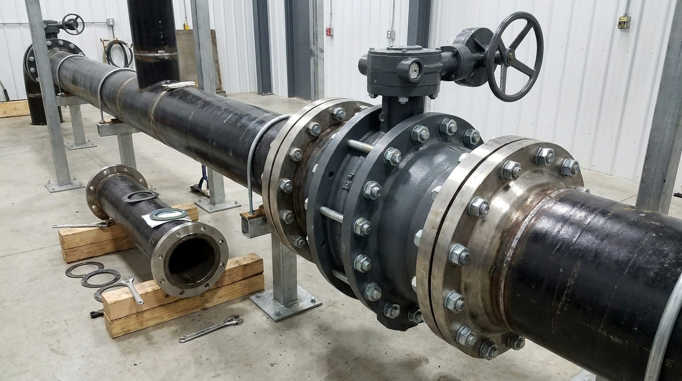
A lug body butterfly valve is the right choice when each pipe flange must connect independently to the valve, especially where downstream piping may be removed for maintenance. The body has a full pattern of tapped lugs, so short fasteners can secure each flange separately instead of clamping the whole assembly with through-bolts.
That mounting difference can prevent a shutdown during a pump, strainer, or pipe-spool replacement. It can also create a serious specification error if “lug” is treated as proof of dead-end capability, pressure rating, or flange compatibility. Although it uses the same disc-and-shaft principle as other industrial butterfly valve configurations, the lug body must be checked as a pressure-retaining mechanical interface, not just selected by valve size.
What Does the Lug Body Change?
The lug body changes how the valve connects to the piping; it does not change the basic quarter-turn operating principle. A shaft rotates the disc through roughly 90 degrees between the closed and open positions, while the seat seals around the disc edge when the valve closes.
In a true full-lug design, every flange bolt position has a tapped lug in the valve body. Fasteners enter from each pipe flange and engage the valve independently. Some wafer bodies have a few unthreaded alignment ears, but those ears do not create the same load path and should not be mistaken for full lugs.
This distinction matters most when a flange on one side will be disconnected. With a full-lug body, the other flange can remain mechanically attached. Whether the valve may safely retain pressure in that condition is a separate rating question covered below.
Lug Body vs Wafer Body
A lug body provides independent flange attachment, while a wafer body relies on fasteners spanning or clamping both flanges. The table shows the practical consequences without assuming one body style is universally better.
| Decision point | Lug body | Wafer body |
|---|---|---|
| Flange attachment | Each flange bolts independently into tapped lugs | Both flanges clamp the valve in one assembly |
| Typical fasteners | Short cap screws or other drawing-specified fasteners | Through-bolts or studs with nuts |
| One-side pipe removal | Mechanically possible if the valve is rated and installed for it | Normally not permitted because the assembly depends on both flanges |
| Weight and purchase cost | Usually higher because of added body material and machining | Usually lower and lighter |
| Pressure capability | Determined by the complete valve rating | Determined by the complete valve rating |
| Best fit | Maintenance isolation, removable downstream equipment, or a defined dead-end duty | Permanent in-line duty where both flanges remain connected |
The key selection point is maintenance access, not a blanket pressure claim. A wafer and a lug valve can share the same in-line pressure class, seat design, and test requirement. Conversely, a lug body does not make an unsuitable seat, disc, shaft, or actuator acceptable for a demanding service. For a broader body-style decision, compare the actual maintenance case in this lugged-versus-wafer selection guide.
Dead-End Service Needs Its Own Rating
Dead-end service is acceptable only when the manufacturer’s data sheet or approved drawing states the allowable pressure, direction, and installation condition. The presence of threaded lugs proves independent attachment, but it does not prove that the body, seat, shaft, and fasteners can retain the valve’s full in-line rating with one flange removed.
Three ratings can be different:
- The shell rating describes the pressure boundary of the valve body.
- The seat rating describes the differential pressure the closed valve can seal.
- The dead-end rating describes the condition with one side unsupported by connected piping.
Use the lowest applicable limit. Also confirm whether the dead-end rating is unidirectional or bidirectional, which side must face pressure, and whether a downstream safety flange is required. If the drawing is silent, do not infer the rating from the word “lug,” the nominal pressure class, or a similar model.
Before anyone removes downstream piping, isolate other energy sources, depressurize and drain the section being opened, verify the valve position and pressure boundary, and follow the site’s lockout procedure. A valve rated for dead-end duty is an engineered isolation component, not permission to work on a pressurized line without a task-specific safety plan.
Prove the Valve Will Fit the Line
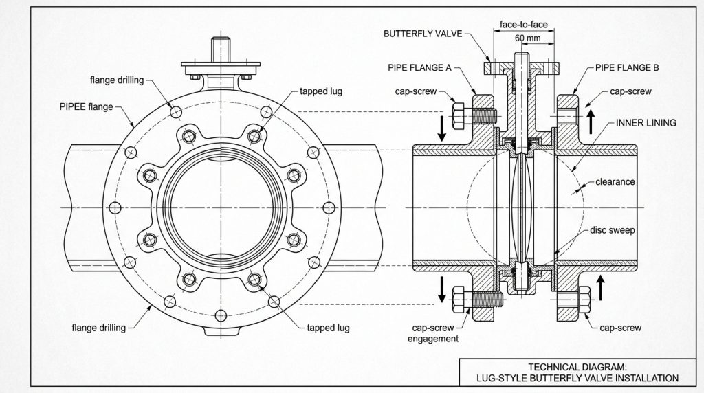
Fit is proven by matching the flange system, valve drawing, fasteners, face-to-face dimension, and disc sweep. Nominal size alone cannot confirm any of these interfaces.
Match the flange drilling first
Start with the piping flange standard and pressure class. The current ASME B16.5 scope covers dimensions, bolt-hole designation, bolting, gaskets, and flange joints for its stated NPS and class range. EN, JIS, and other flange systems use different drilling and fastener conventions, so do not translate a valve from one system by nominal size alone.
Then match the valve’s bolt circle, hole count, thread diameter, pitch, and usable tapped depth. RUITO’s lugged butterfly valve bolt-chart method separates flange drilling from valve-specific cap-screw length. That distinction prevents two opposite failures: too little thread engagement and a screw that bottoms out or contacts the screw entering from the other side.
Check face-to-face and disc clearance
Face-to-face length must match the piping layout, especially for a replacement valve. ISO 5752:2021 defines basic face-to-face series for butterfly valves and other metal valves in flanged piping, but the purchase specification still has to identify the applicable series and valve pattern.
The drawing must also show the disc envelope at full opening. Heavy-wall pipe, lined pipe, reducing spools, or a small flange bore can interfere with the disc even when the bolt holes align. Cycle the installed valve carefully before commissioning and investigate any hard stop; forcing the actuator can damage the disc edge, seat, shaft, or gearbox.
Match the Trim and Operator to the Service
The lug body solves a piping-attachment problem, while the trim and operator solve the media, sealing, and movement problems. Specify operating and design pressure, operating and design temperature, fluid composition, solids, corrosion risk, required shutoff direction, cycle frequency, and whether the valve will isolate or throttle.
For resilient-seated service, common seat options include EPDM, NBR, FKM, and PTFE-based designs, but compatibility depends on the exact fluid and temperature. Metal-seated and offset designs may suit higher-temperature or abrasive duties, yet their leakage criteria and torque can differ from soft-seated concentric valves. Select the complete material set—body, disc, shaft, seat, liner, bushings, and external fasteners—rather than choosing only the body material.
Actuator sizing must use valve torque data at the specified differential pressure and temperature. Check seating, unseating, running, and dynamic torque as applicable, then apply the project’s margin and supply conditions. A matching mounting pad proves mechanical fit; it does not prove that a pneumatic, electric, hydraulic, or manual operator can move and seat the valve under the worst required condition.
Put the Required Evidence in the RFQ
A reliable RFQ makes dead-end duty and every installation interface explicit, then requires documents that let the project team verify them. API’s current listing identifies API Standard 609 as covering double-flanged, lug-, wafer-, and butt-welding-end butterfly valves; however, naming the standard alone does not define your service.
Include these items in the requisition:
- Valve size, body style, pressure class or CWP basis, and applicable standard edition
- Media, solids content, operating and design pressure, and operating and design temperature
- Flange standard, facing, bore, gasket or liner arrangement, and face-to-face series
- Body, disc, shaft, seat, liner, bushing, and fastener materials
- Maximum differential pressure, flow direction, shutoff direction, and leakage acceptance criteria
- Dead-end requirement, allowable dead-end pressure, pressure side, and whether a downstream flange is required
- Actuator type, fail position, available power or air supply, cycle duty, accessories, and torque basis
- Approved dimensional drawing showing drilling, tapped depth, cap-screw length, disc sweep, and actuator envelope
- Required material certificates, dimensional report, shell and seat test records, coating report, and inspection hold points
For more detail on category, rating basis, face-to-face fit, and purchase data, use this API 609 service-condition checklist as a companion to the project specification.
For its butterfly-valve program, RUITO lists lug connections alongside wafer and flanged options, with ductile iron, carbon steel, stainless steel, duplex, and multiple seat and disc choices across the broader range. Its published quality workflow includes dimensional checks of flange drilling and face-to-face length, hydrostatic shell testing, seat leakage testing, and traceable reports. These are portfolio capabilities, not proof that every configuration shares one rating; the quotation, data sheet, drawing, and test plan must identify the exact lug valve offered for your duty.
Choose From the Maintenance Case
A lug body butterfly valve earns its added weight and machining when independent flange attachment supports a real maintenance or end-of-line requirement. Choose a wafer body when both flanges will remain connected and the lug function adds no operational value. In either case, the pressure rating comes from the complete valve, not from the body-style label.
For a project review, send the line size, flange standard, pressure and temperature, media, material requirements, actuator duty, and dead-end condition through RUITO’s contact page. The engineering review can then confirm the body pattern, rating boundary, drawing details, and test documentation before the valve and fasteners are released for purchase.
FAQ
Is a lug body butterfly valve the same as a flanged valve?
No. A lug body has individual tapped projections around a compact body, while a flanged butterfly valve has integral full flanges. Both can connect independently to the piping, but their face-to-face dimensions, weight, bolting, ratings, and installation envelopes may differ.
Does a lug body butterfly valve need separate gaskets?
It depends on the seat and body design. Some resilient liners form the flange seal and prohibit extra gaskets, while other designs require a defined gasket. Follow the model-specific drawing and installation instructions because an unnecessary or incorrect gasket can change compression and disc clearance.
Is a lug body always bidirectional?
No. Bidirectional in-line shutoff and bidirectional dead-end service are separate claims. Confirm the rated pressure direction, preferred flow direction, seat test direction, and dead-end pressure side on the data sheet and approved drawing.