
You avoid fit mistakes by checking JIS 10K butterfly valve dimensions against the actual flange gap, bore, drilling, operator space, and drive interface. Nominal diameter alone cannot establish fit. Collect the model-specific dimensions before ordering so the installation team can identify a mismatch while there is still time to change the specification.
1. What JIS 10K butterfly valve dimensions should you collect?
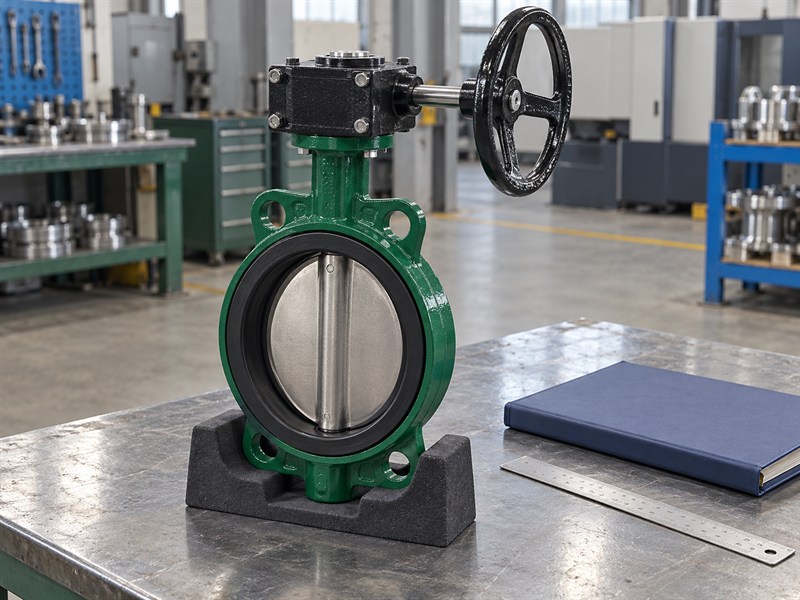
Collect JIS 10K butterfly valve dimensions for the body, mating connection, moving disc, drive, and complete installation envelope. Keep each measurement tied to the exact nominal size, construction, materials, and operator. A drawing for a similar valve can look convincing while describing a different installation.
Start with the valve's nominal diameter and pressure-class designation, then identify its actual body style. A wafer body fits between mating flanges; a double-flanged body has its own end connections. A lug body introduces threaded connections and engagement requirements. These differences affect far more than the width shown in a catalogue photograph.
Which drawing should control the order?
Request the supplier's general arrangement drawing for the proposed assembly and record its revision. Read every dimension with its units, datum, and tolerance.
- Identify the size and complete supplied configuration.
- Separate body dimensions from operator dimensions.
- List any interface that needs project approval.
| Dimension group | Information to collect |
|---|---|
| Body | Face-to-face length and external profile |
| Connection | Facing, drilling, bore, and fastener details |
| Assembly | Disc sweep, drive interface, height, and access |
Use that approved drawing as the receiving and installation reference rather than rebuilding the specification from photographs.
2. How do JIS 10K butterfly valve dimensions define body length?
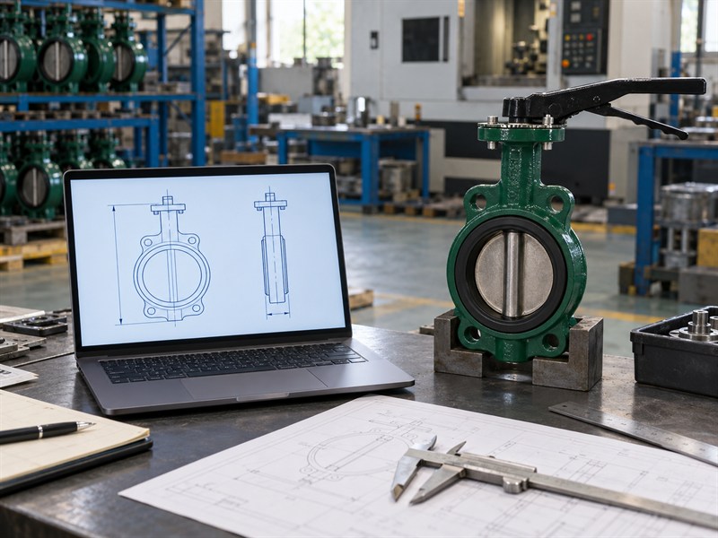
JIS 10K butterfly valve dimensions define body length through the specified face-to-face measurement and its drawing datums. Read the actual dimension rather than assuming that every valve of one nominal size uses the same length. The applicable construction and dimensional series must be identified in the purchase specification.
The Japanese Valve Manufacturers' Association standards list identifies JIS B 2002 as the valve dimensional standard. That reference does not replace the selected valve's drawing. Confirm the required series, size, and construction with the supplier, particularly when replacing an installed valve from another manufacturer or changing from a lever to a gearbox assembly.
What happens when the site gap differs?
If an approved drawing calls for a 52 mm installation length and a survey records 50 mm, the 2 mm difference needs engineering review. This is an illustrative comparison, not a universal DN-to-length table.
- Measure the defined flange-face gap without forcing alignment.
- Check the supplier's stated dimensional tolerance.
- Resolve any mismatch before the installation outage.
| Record | Keep separate |
|---|---|
| Required body length | Drawing value and tolerance |
| Available site gap | Measured condition and measurement method |
| Proposed resolution | Written engineering approval |
Do not assume seat compression or an extra gasket can absorb an unapproved difference.
3. Which JIS 10K butterfly valve dimensions control flange fit?
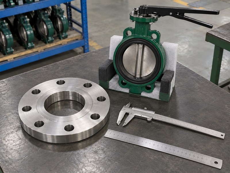
JIS 10K butterfly valve dimensions control flange fit through the bolt pattern, bore, facing, and available fastener path. Record the mating flange standard, material, class, and nominal size alongside those measurements. A pressure designation cannot supply the missing geometry.
A wafer valve may have a centering arrangement suitable for several connection patterns, but the supplier must confirm the specific size and mating standard. A lug valve needs a different review of thread type, bolt length, and effective engagement. Never transfer a through-bolt length from a wafer assembly directly to a lugged installation.
Which measurements belong on a flange survey?
Provide a dimensioned record that distinguishes the bolt-circle diameter from the flange outside diameter. Include the actual bore and face arrangement.
- Count the holes and record their diameter.
- Measure the bolt circle using an appropriate method.
- Identify any neck, lining, or facing restriction.
| Feature | Compare with the approved assembly |
|---|---|
| Bolt circle and hole count | Fastener and centering arrangement |
| Flange bore | Disc clearance envelope |
| Facing | Seat or gasket installation requirement |
Stop the review when a dimension remains unknown; an approximate measurement should not become an approved interface value.
4. How do JIS 10K butterfly valve dimensions affect disc travel?
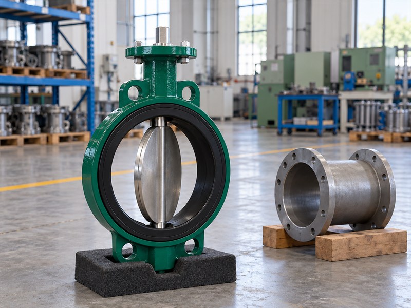
JIS 10K butterfly valve dimensions must include the rotating disc envelope, because the disc can extend beyond the body faces during opening. A valve that fits the flange gap can still contact the adjacent pipe. Check the complete swept path rather than only the closed position.
Actual pipe bore can differ from its nominal designation. Thick walls, internal coatings, flange necks, and nearby reducers can reduce the available opening. A supplier's minimum mating-bore requirement is therefore a separate dimension from the valve's nominal diameter or closed disc diameter.
How should the drawing show clearance?
Ask the supplier to identify the relevant disc projection and unobstructed bore requirements for the offered valve. Compare both sides of the installation.
- Check the bore at the valve and adjacent restrictions.
- Record internal lining thickness where relevant.
- Confirm clearance throughout the approved travel.
| Check position | Possible obstruction |
|---|---|
| At the flange | Facing, neck, or internal lining |
| Beside the body face | Pipe wall or reducer |
| Across full travel | Any intrusion into the disc envelope |
If the assembled valve binds, investigate the physical interference before changing drive settings or applying more torque.
5. Which JIS 10K butterfly valve dimensions describe the operator?
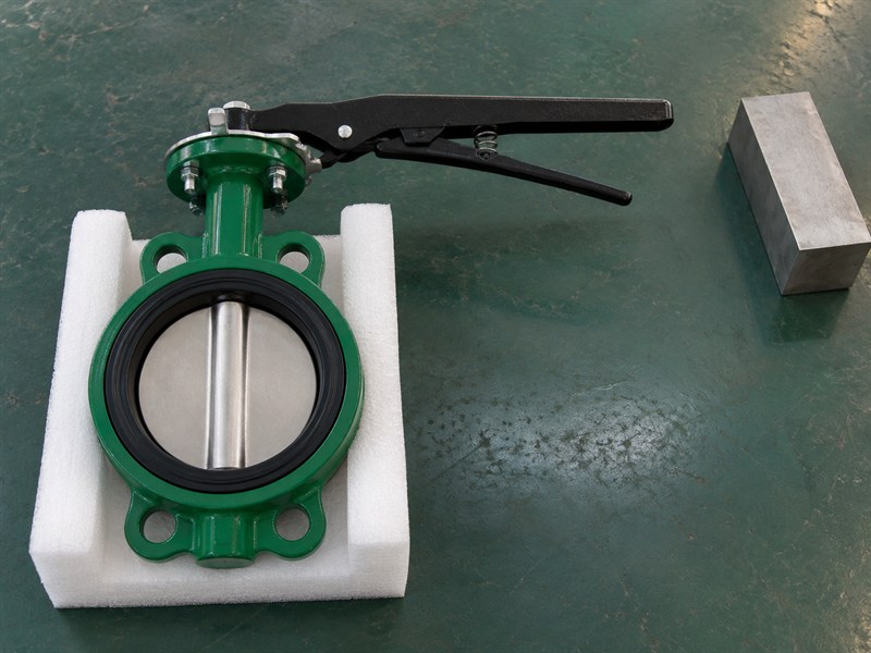
JIS 10K butterfly valve dimensions should describe the complete operator envelope as well as the body. A lever, worm gearbox, pneumatic actuator, or electric actuator can change overall height, width, weight, and access requirements. Approval of a bare valve drawing cannot establish the fit of an automated assembly.
Check the operator against nearby pipework, insulation, structural members, and enclosure doors. Leave space for normal operation and planned maintenance. A handwheel that clears the pipe may still sit where a person cannot reach it safely. An actuator may fit during assembly but lack room for removal later.
Which access dimensions should you request?
Ask for the entire supplied arrangement, including brackets, switches, solenoids, and cable or air-line connections where fitted.
- Record the lever sweep or handwheel envelope.
- Check access to fasteners and adjustment points.
- Leave the required actuator removal and lifting space.
| Operator feature | Installation question |
|---|---|
| Lever length | Can it complete its full travel? |
| Handwheel position | Can an operator reach and turn it? |
| Actuator and accessories | Is service access available? |
Review the assembly in the actual plant layout before freezing the mounting orientation.
6. Which JIS 10K butterfly valve dimensions define the drive?
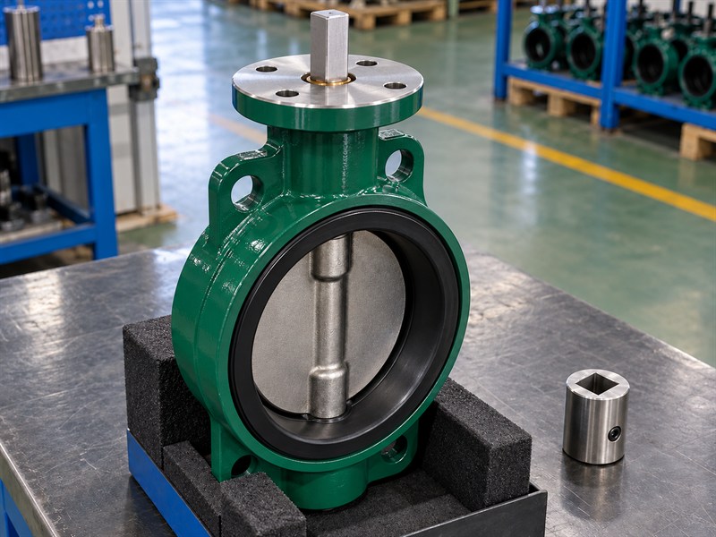
JIS 10K butterfly valve dimensions define the drive through the mounting face, shaft end, coupling, bracket, and operator position. A matching bolt pattern is only one part of that interface. Confirm shaft shape, size, engagement length, orientation, and allowable loads for the exact assembly.
For an actuator replacement, compare the approved drive drawing with the existing valve and its required torque. A coupling that appears to fit can bottom out, engage too little shaft, or leave an unsupported load path. The mounting standard also cannot establish the valve's torque requirement by itself.
What belongs in the drive interface record?
Keep dimensions and operating requirements together when requesting a butterfly valve actuator sizing review. Include the conditions under which the valve must operate.
- Identify the mounting pattern and stem orientation.
- Record coupling engagement and bracket dimensions.
- Confirm torque capacity through every drive component.
| Interface item | Required information |
|---|---|
| Mounting face | Pattern, holes, orientation, and drawing |
| Shaft end | Shape, size, and usable engagement |
| Coupling and bracket | Fit, support, and load capacity |
Require a documented interface review when changing either the valve or its operator.
7. How do JIS 10K butterfly valve dimensions guide site surveys?
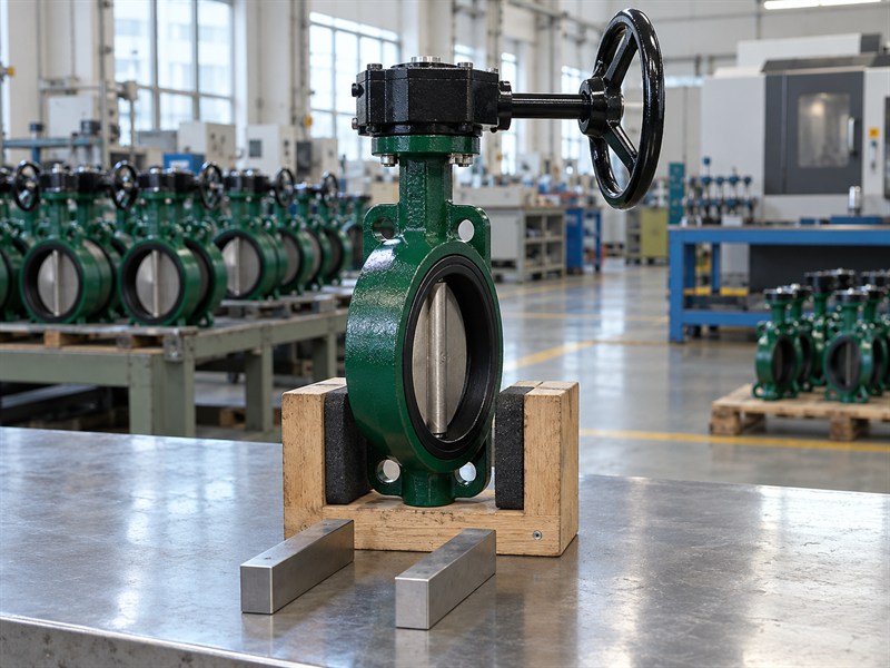
Use JIS 10K butterfly valve dimensions to prepare a site survey that records the installation as it exists. Include the flange gap and geometry, pipe bore, orientation, supports, and surrounding obstructions. Photographs help identify the arrangement, but they cannot replace measurements with known reference points.
For a replacement, inspect the existing valve's identity and any available drawings before planning the survey. The installed pipework may differ from an older layout drawing. Record any discrepancy and identify which dimensions were measured directly, taken from a current drawing, or still need confirmation.
What should the survey team hand over?
Provide one controlled record for the supplier and installation team. Use consistent units and identify the measurement direction and datum.
- Mark dimensions on an annotated installation sketch.
- Record obstructions above and beside the operator.
- Identify access and isolation requirements for installation.
| Survey field | Why it belongs in the record |
|---|---|
| Measurement source | Distinguishes measured and drawing values |
| Datum and units | Prevents incompatible comparisons |
| Unresolved item | Keeps missing information visible |
Check orientation requirements with the selected valve's instructions and the butterfly valve orientation guide before approving the final arrangement.
8. How should JIS 10K butterfly valve dimensions be inspected?
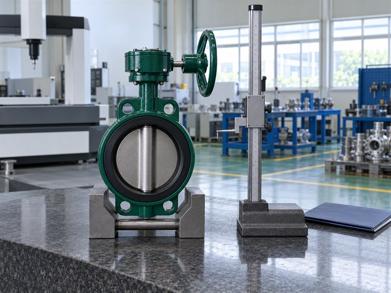
Inspect JIS 10K butterfly valve dimensions against the approved drawing and its stated tolerances. Identify the measuring method, instrument, datum, and acceptance criteria before recording a result. A dimension without a defined reference or tolerance cannot support a clear acceptance decision.
Separate the inspection of body length, connection features, operator envelope, and drive interface. Use suitable calibrated equipment and protect seats, sealing faces, and finished shafts during measurement. A dimensional inspection does not establish material identity, pressure integrity, or seat leakage performance; those require their own agreed records.
How do you handle a measurement outside tolerance?
Record the actual result and hold the affected item for disposition. Ask for an approved resolution rather than changing the acceptance criteria after measuring it.
- Identify the valve, size, configuration, and drawing revision.
- Record specified and measured values separately.
- Track each nonconformity through a documented decision.
| Inspection record | Information to retain |
|---|---|
| Requirement | Drawing dimension and tolerance |
| Result | Measurement, method, and instrument |
| Disposition | Acceptance, correction, or approved deviation |
Link the completed dimensional record with the delivered product identifier and shipment documentation.
9. Which JIS 10K butterfly valve dimensions affect repeat orders?
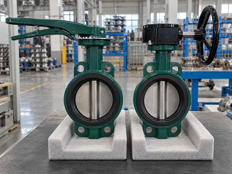
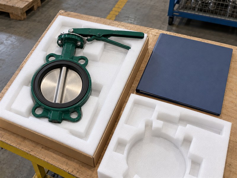
Freeze JIS 10K butterfly valve dimensions that affect interchangeability, assembly, maintenance, and packing on repeat orders. Keep the approved drawing and configuration revision with your purchasing record. A repeated nominal size and class description cannot establish that the next batch uses the same operator or interfaces.
An OEM may depend on fixed pipe-spool lengths, assembly fixtures, actuator brackets, or packing cavities. A changed neck height or lever length can cause a production problem without changing the valve's nominal designation. Require notice and engineering approval before the supplier changes a controlled dimension.
What should a repeat purchase order identify?
Refer to the frozen drawing and material configuration, then state quantities, inspection requirements, and permitted changes. Keep commercial delivery conditions alongside the technical baseline.
- Identify the approved drawing and operator arrangement.
- Define the dimensions requiring incoming inspection.
- Check support and operator clearance in the packing design.
| Controlled item | Possible effect of a change |
|---|---|
| Body and flange interface | Pipe-spool fit or fastener mismatch |
| Drive and operator envelope | Assembly or maintenance obstruction |
| Packing envelope | Unsupported body or loaded operator |
Send the drawing and measured installation record when you contact RUITO to review an order-specific configuration before purchase.
10. What JIS 10K butterfly valve dimensions questions recur?
Q1: Can I use nominal diameter as the actual bore measurement?
No; review JIS 10K butterfly valve dimensions using separate checks for nominal size and actual bore. Check the valve opening, mating flange bore, pipe bore, and disc-clearance requirements separately using the approved drawing and installation survey.
Q2: Can I replace one wafer valve with another of the same size?
Only after checking the complete interface and service requirements. Compare body length, drilling, facing, bore clearance, materials, ratings, drive arrangement, and operator access rather than relying on nominal size alone.
Q3: How do I know which drawing letter means body length?
Read the drawing's dimension arrows and datums. Letters such as L, H, and D can be assigned differently across documents. Confirm the defined measurement instead of assuming one supplier's notation applies to another.
Q4: Can a correct mounting pattern prove an actuator will fit?
No. Check the shaft end, coupling engagement, bracket, orientation, torque, and full assembly envelope. A matching pattern cannot establish the capacity or geometry of the remaining drive components.
Q5: What's the best way to avoid repeat-order fit problems?
Keep a controlled approved drawing and configuration record. Reference them on the purchase order and require approval before interface changes. Inspect the designated dimensions when receiving the next batch.