
Match the valve duty, JIS connection, actuator torque, minimum air supply, and required failure action before buying a JIS pneumatic butterfly valve. An actuator selected at catalogue air pressure can stall when pressure at the valve falls during operation. Use one assembly data sheet to define both the valve and its control package.
1. How does a JIS pneumatic butterfly valve work?
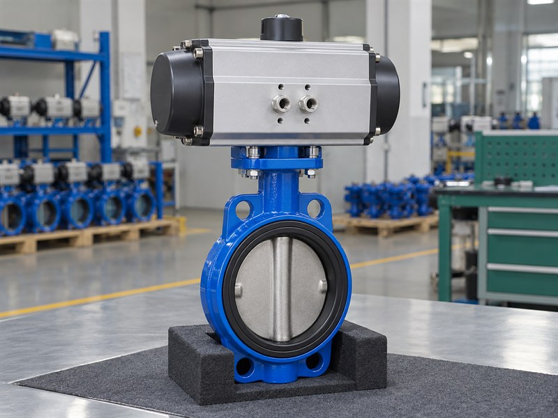
A JIS pneumatic butterfly valve uses compressed air to drive an actuator that rotates the valve disc through its operating travel. The actuator converts air-driven movement into shaft rotation. The valve body, disc, seat, and shaft still determine the process-side service limits and sealing arrangement.
Quarter-turn actuators commonly use rack-and-pinion or scotch-yoke mechanisms. Their available torque depends on the selected mechanism, actuator size, supply conditions, and any spring arrangement. Read the manufacturer's output data for the exact actuator rather than assuming that every pneumatic unit has the same torque profile.
Which parts belong in the assembly review?
Include the mechanical drive and the control accessories. A valve body quotation and an actuator quotation can leave the coupling, bracket, solenoid, or feedback package undefined.
- Identify the valve and actuator configurations separately.
- Check the complete stem-to-actuator drive path.
- Specify the required control and feedback accessories.
| Assembly part | Requirement to define |
|---|---|
| Valve | Fluid, ratings, materials, and connection |
| Actuator | Output, supply, duty, and failure action |
| Controls | Solenoid, signals, feedback, and enclosure |
Ask the supplier to identify the complete delivered assembly on one approved drawing.
2. What JIS pneumatic butterfly valve connection checks apply?
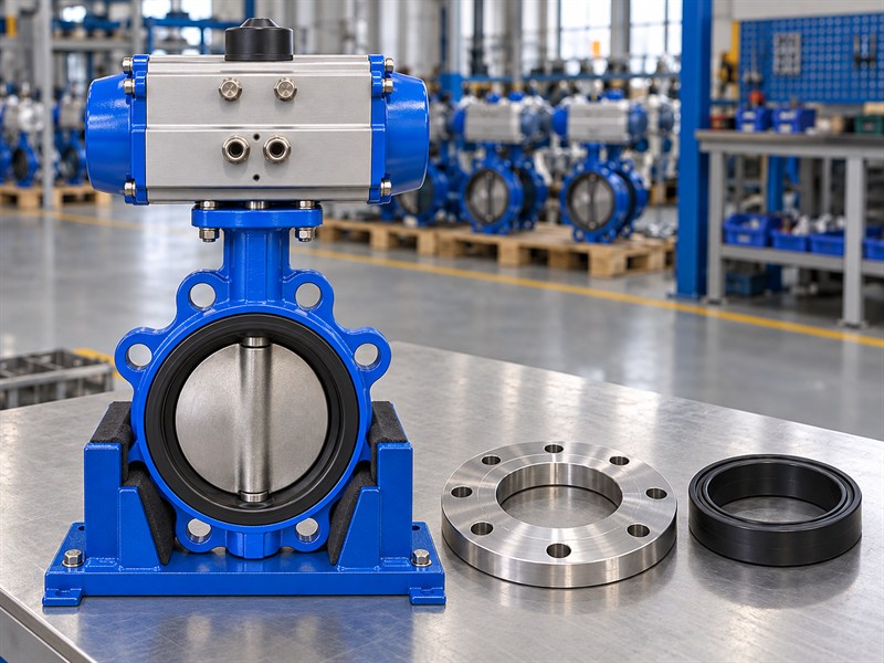
A JIS pneumatic butterfly valve needs an approved mating connection and a process-side configuration suited to the actual fluid. The pneumatic operator does not define the flange geometry. Confirm the flange standard, class, facing, bore, drilling, and required fasteners for the offered nominal size.
Identify the applicable valve design route separately. The published scope of JIS B 2032:2024 concerns wafer type rubber-seated butterfly valves for general facilities. Different constructions or application-specific requirements need their own review. A familiar actuator cannot establish compliance of the valve beneath it.
Which service details should the supplier receive?
Provide the complete fluid composition and operating conditions. RUITO's documented water, oil, and clean-gas configurations have separate material and service limits.
- State operating pressure, temperature, and closing differential.
- Identify seat, disc, shaft, and auxiliary seal materials.
- Confirm disc clearance through both mating connections.
| Requirement | Evidence to request |
|---|---|
| JIS connection | Size-specific interface drawing |
| Fluid suitability | Complete material and service assessment |
| Installation fit | Body length, bore clearance, and envelope |
Keep the approved valve configuration in the assembly record when selecting or replacing the actuator.
3. What failure action does a JIS pneumatic butterfly valve need?
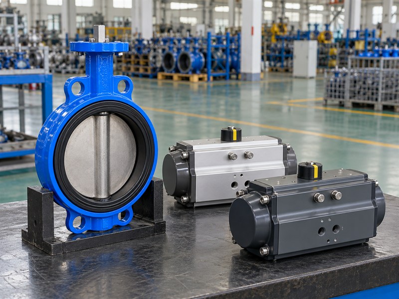
A JIS pneumatic butterfly valve needs a failure response defined by the process requirement and verified for the complete assembly. State what should happen on loss of air and on loss of electrical power to the control package. Those events can produce different responses depending on the selected arrangement.
A spring-return actuator uses stored spring energy for one direction of travel. Its available spring torque must suit the valve throughout that movement. A double-acting actuator uses air in both directions; process forces, leakage, and the control arrangement can affect its position after air loss. Specify any required holding response explicitly.
How do you define a usable failure requirement?
Record the target position, allowed response time, process differential, and available energy conditions. Then ask the supplier to demonstrate the proposed arrangement against that requirement.
- Specify fail-open, fail-closed, or another required response.
- Review air-loss and power-loss conditions separately.
- Confirm the complete actuator, solenoid, and valve arrangement.
| Arrangement | Confirmation needed |
|---|---|
| Spring-return | Spring output throughout the required stroke |
| Double-acting | Defined response under the specified failure conditions |
| Complete package | Verified action, indication, and timing |
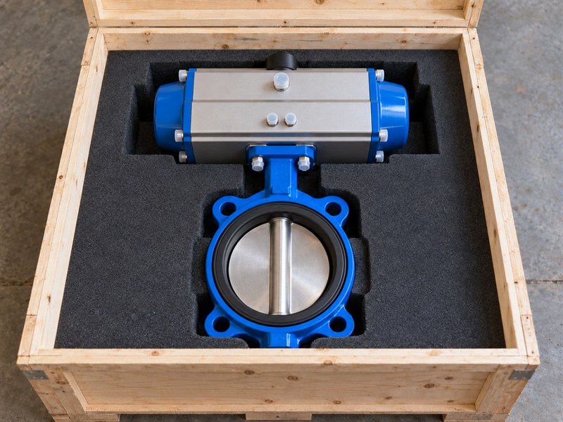
Do not infer a demonstrated failure response from an actuator housing photograph or a short catalogue label.
4. How do you size a JIS pneumatic butterfly valve actuator?
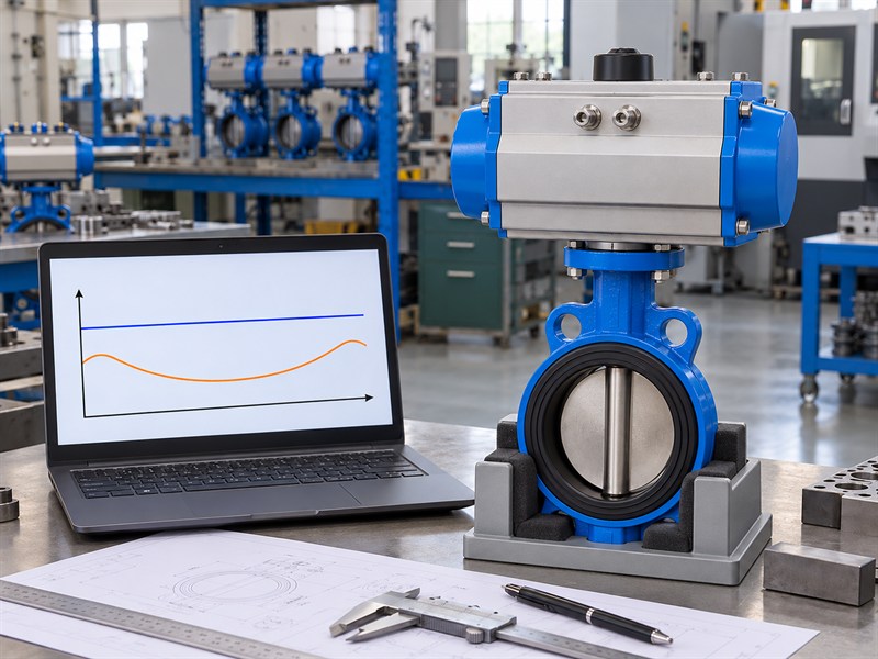
Size a JIS pneumatic butterfly valve actuator against the valve's required torque at the minimum available air supply. Compare output and demand throughout the required travel, including breakaway, running, and seating conditions. State the process differential, temperature, media, cycling duty, and agreed sizing margin.
The illustrative chart compares available output in blue with valve demand in orange; it does not provide a model-specific rating. Obtain the actual valve and actuator curves for the selection. Spring-return units also need review of the air-driven and spring-driven strokes under their respective limiting conditions.
Which mechanical limits should the sizing review include?
Request a butterfly valve actuator sizing review covering the full drive path. Greater available output does not remove the need to check allowable component loads and travel settings.
- Check output at the minimum specified supply.
- Confirm stem, coupling, bracket, and actuator capacity.
- Review stops and the maximum available drive output.
| Sizing input | Why it is needed |
|---|---|
| Valve torque data | Defines demand at the stated duty |
| Actuator output curves | Defines available output across travel |
| Supply range and margin | Defines the accepted selection basis |
Keep the sizing calculation with the approved assembly documents so replacements receive the same review.
5. Which JIS pneumatic butterfly valve air-supply checks matter?
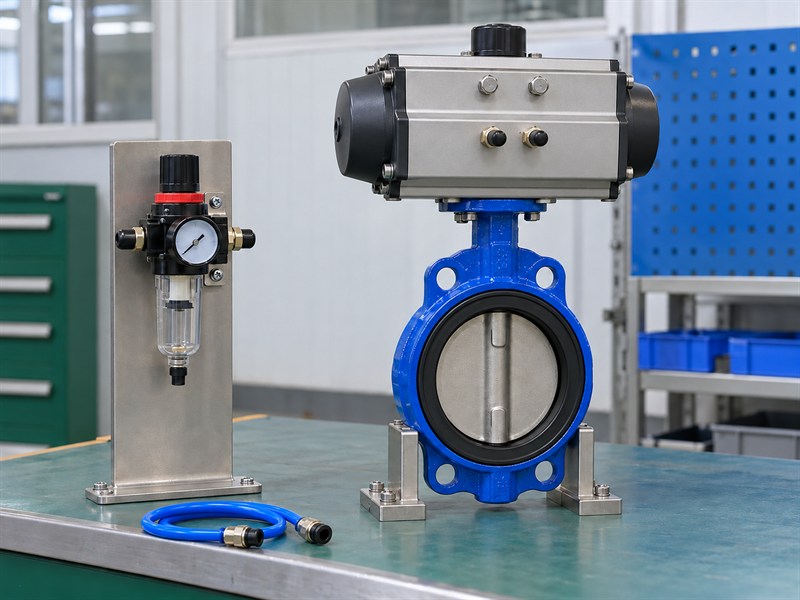
A JIS pneumatic butterfly valve needs air of the pressure, quality, and flow capacity specified for its actuator and accessories. Record the available supply at the assembly during the required operating duty. A header rating alone cannot show the pressure drop through local tubing, filters, regulators, and solenoids.
Confirm filtration, dryness, and lubrication requirements from the selected manufacturer's instructions. Water, contamination, unsuitable lubricant, or restricted flow can affect movement and repeatability. Tube size, line length, fittings, and accessory flow capacity also influence travel time and the available pressure while the actuator moves.
What should the site team record during commissioning?
Use the approved procedure and suitable instruments to check the supply conditions and operation. Record settings and results rather than relying on the appearance of a regulator gauge.
- Confirm the permitted minimum and maximum supply.
- Check tube connections and accessory flow capacity.
- Record required air quality and maintenance tasks.
| Supply field | Information to retain |
|---|---|
| Pressure range | Conditions at the actuator assembly |
| Air quality | Manufacturer-specified preparation requirements |
| Flow path | Tubing and accessory configuration |
Investigate slow or incomplete travel through the supply and mechanical checks before increasing pressure or drive force.
6. How do you specify JIS pneumatic butterfly valve controls?
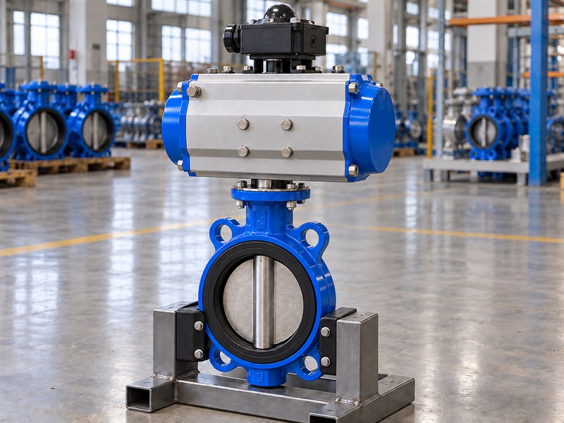
Specify JIS pneumatic butterfly valve controls through the required command, solenoid operation, feedback, power supply, and environmental conditions. Identify how the plant control system requests movement and how it confirms the resulting position. The solenoid configuration must suit the actuator arrangement and required failure response.
Check coil voltage, electrical connection, enclosure requirements, and any project-specific area classification. Define the feedback devices and their signals, then verify their relationship with actual valve travel. A control command or a switch indication cannot establish seat leakage performance under process conditions.
Which failure conditions belong in the control description?
Describe the response to loss of command power, solenoid power, air supply, and any required emergency signal. Keep the complete package arrangement clear.
- Identify the required command and feedback signals.
- Specify the solenoid's de-energized arrangement.
- Confirm accessory mounting and connection details.
| Control item | Requirement to record |
|---|---|
| Command | Supply, signal, and operating mode |
| Feedback | Device, signal, and verified position relationship |
| Failure response | Defined action for each specified event |
Freeze the control package with the mechanical assembly so a substituted accessory receives a documented review.
7. How do you mount a JIS pneumatic butterfly valve correctly?
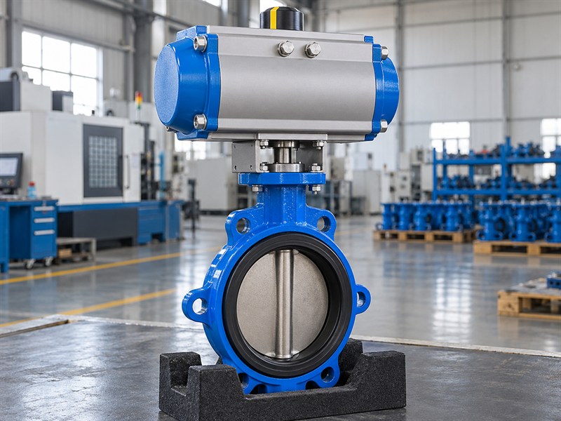
Mount a JIS pneumatic butterfly valve using the approved stem, coupling, bracket, orientation, and fasteners. The actuator must transmit torque through a correctly engaged and supported drive path. Confirm that the assembly drawing matches the supplied components before installation or replacement.
Check the coupling for the specified shaft form and engagement. Review access to mounting bolts, tubing, solenoids, feedback devices, and service points. Pipe supports and valve installation also matter: flange misalignment, excessive seat compression, or disc interference can increase resistance and disturb an otherwise suitable actuator selection.
What should you inspect before operating the assembly?
Follow the manufacturer's isolation and stored-energy procedures before mechanical work. Use the approved butterfly valve orientation and installation requirements for the selected configuration.
- Confirm drive engagement and bracket support.
- Check full disc clearance and permitted orientation.
- Verify stops, indication, and accessory access.
| Mounting check | Acceptance basis |
|---|---|
| Drive interface | Approved dimensions and load capacity |
| Valve installation | Manufacturer's assembly and tightening procedure |
| Complete travel | Unobstructed movement and agreed settings |
Investigate binding or unexpected resistance before changing the actuator's supply or travel settings.
8. How should a JIS pneumatic butterfly valve be tested?
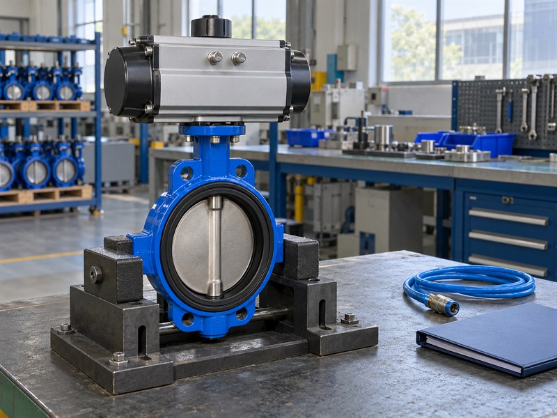
Test a JIS pneumatic butterfly valve against an agreed inspection and functional acceptance plan. Valve pressure and leakage tests address process-side requirements. Assembly travel, indication, controls, and failure-response tests address different questions and need their own specified conditions and records.
Define supply conditions, process differential where applicable, operating sequence, response time, signals, and acceptance criteria before testing. Verify the required air-loss and power-loss responses through the approved procedure. A successful unloaded bench stroke does not establish performance under every operating differential or supply condition.
Which evidence should accompany the shipment?
Link the results with the valve, actuator, controls, configuration, and drawing revision. Retain the actual observations and the required criteria separately.
- Record full travel and position indication.
- Document the specified control and failure events.
- Identify instruments, test conditions, and acceptance decisions.
| Test record | What it establishes |
|---|---|
| Valve pressure and seat tests | Performance under the stated valve-test conditions |
| Assembly functional test | Travel, controls, and feedback under stated conditions |
| Failure-response check | Recorded action for the specified event and duty |
Keep factory acceptance evidence alongside the site commissioning requirements rather than treating one as a substitute for the other.
9. What JIS pneumatic butterfly valve order documents are needed?
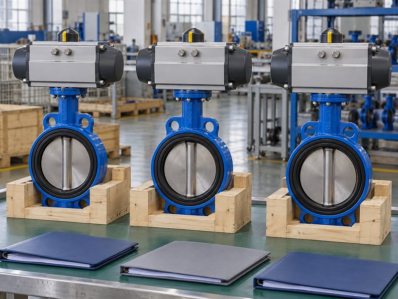
A JIS pneumatic butterfly valve order needs a controlled valve data sheet, assembly drawing, sizing basis, control description, material list, and inspection schedule. Identify the supplied accessories and permitted alternatives. That baseline makes quotations from pneumatic butterfly valve suppliers easier to compare.
State the fluid, duty, JIS interface, nominal size, operating cycle, supply range, command signals, feedback, and failure action. Include document dates, inspection hold points, packing requirements, and delivery conditions. A repeat order should refer to the approved revisions rather than only repeating a short commercial product name.
Which changes should require approval?
Define the technical change process for the seat, actuator, coupling, bracket, solenoid, feedback device, and control arrangement. Those substitutions can affect the complete assembly's behavior.
- Freeze the approved mechanical and control documents.
- List spare parts for the actual supplied configuration.
- Require review before controlled-component changes.
| Order attachment | Purpose |
|---|---|
| Valve and assembly data | Defines the complete offered duty and configuration |
| Sizing and control records | Defines output and required operating response |
| Inspection and document list | Defines acceptance and release evidence |
Send the service and control requirements when you contact RUITO to review the complete proposed assembly before purchase.
10. What JIS pneumatic butterfly valve questions do buyers ask?
Q1: Can I use the plant header pressure to size the actuator?
Size a JIS pneumatic butterfly valve using the minimum available pressure at the assembly under the specified operating duty. Local tubing, fittings, filters, regulators, and solenoids can reduce the supply during movement. Record the accepted sizing conditions.
Q2: Does a spring-return label prove the required failure position?
No. Confirm the complete valve, mounting, spring output, control arrangement, process duty, and required response. Demonstrate the agreed action through the approved acceptance procedure.
Q3: Can a double-acting actuator hold position after air loss?
Do not assume it will. The process forces and complete control arrangement affect the response. Specify any required holding behavior and obtain evidence covering the proposed arrangement and failure conditions.
Q4: Can pneumatic operation increase the valve's process rating?
No. Select the valve for its own pressure–temperature, material, seat, and connection limits. Select the actuator supply and output separately, then verify the complete assembly for the required duty.
Q5: What's the best way to compare automated-valve quotations?
Compare the same complete configuration and acceptance basis. Require the valve data, interface drawing, actuator sizing, control description, failure response, inspection records, and supplied-parts list before comparing price.