
Check JIS butterfly valve dimensions against the offered drawing and the actual installation. Record the body length, flange geometry, clear bore, disc sweep, shaft interface, and operator envelope separately. A single size designation cannot tell a replacement team whether the valve will fit between existing flanges or clear the equipment around it.
1. Which JIS butterfly valve dimensions belong on a worksheet?
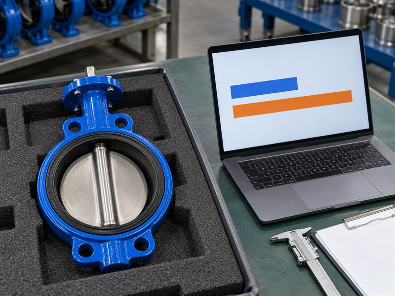
Start a JIS butterfly valve dimensions worksheet with the features that decide whether the complete assembly can be installed and operated. Include axial space between the mating faces, the flange interface, bore restrictions, disc sweep, stem and mounting details, and the space needed for operation and maintenance.
Identify the reference for each entry. A value may come from an approved supplier drawing, a piping drawing, or a site measurement. Keep those sources visible instead of placing them in one unlabeled column. The supplier needs to know which values are requirements and which still need confirmation.
What should the worksheet identify first?
Record the valve tag, location, nominal size, body style, operator, drawing references, and survey date. Add the person responsible for resolving unconfirmed features.
| Worksheet field | Information to retain |
|---|---|
| Assembly identity | Valve tag, construction, operator, and drawing revision |
| Required geometry | Piping interface and available installation space |
| Verification status | Source, measurement method, and unresolved items |
For JIS butterfly valve dimensions, use the worksheet to control the comparison. Keep photographs as supporting records rather than treating a photograph as a dimensional acceptance document.
The unscaled chart illustrates required space in blue and available space in orange. It contains no model-specific dimensions. Obtain the actual values and tolerances before accepting a fit comparison.
2. How do JIS butterfly valve dimensions relate to nominal size?
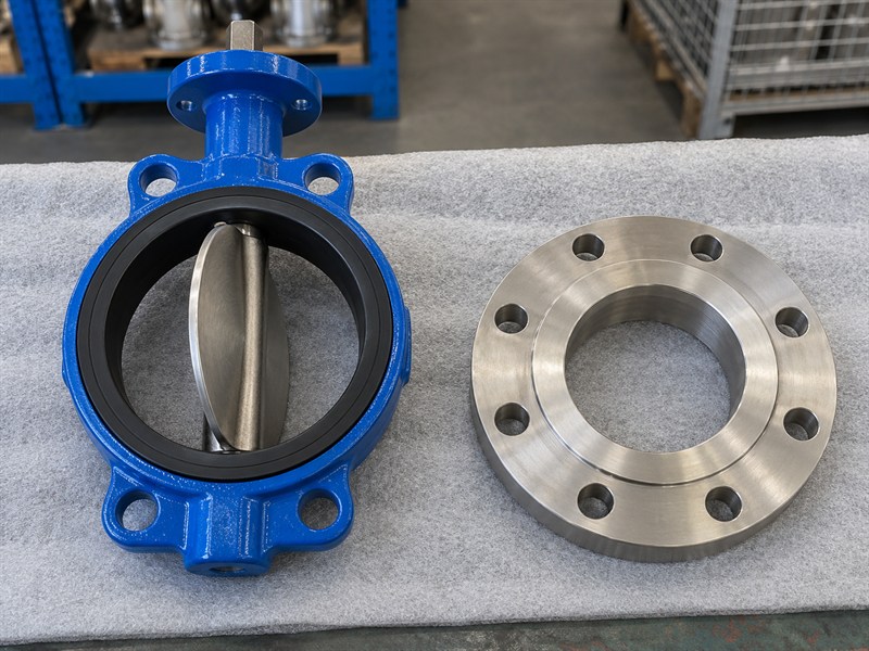
In a JIS butterfly valve dimensions review, nominal size identifies the component’s size category in the piping system. The actual clear opening depends on the selected component and construction. Obtain the bore dimensions needed for the installation instead of assuming that the nominal designation is a measured internal diameter.
Body style also changes the dimensional review. A wafer valve, a lug valve, and a double-flanged valve can require different axial spaces, fasteners, and connection arrangements. Specify the construction before comparing the catalogue rows for a selected size.
How should a supplier's range be interpreted?
RUITO's documented wafer families include DN50–600 PN10/PN16 configurations. A requested JIS interface still needs order-specific drawing confirmation. That range statement does not establish the bore, body length, or JIS compatibility of every proposed configuration.
| Size-related field | What it establishes |
|---|---|
| Nominal size | Component size designation |
| Actual clear bore | Space available for flow and disc movement |
| Body construction | Installation and connection arrangement to review |
Keep units clear when documents use different designation systems. Resolve the offered size and construction before accepting any dimensional cross-reference supplied during quotation.
3. How do you check JIS butterfly valve dimensions for body length?
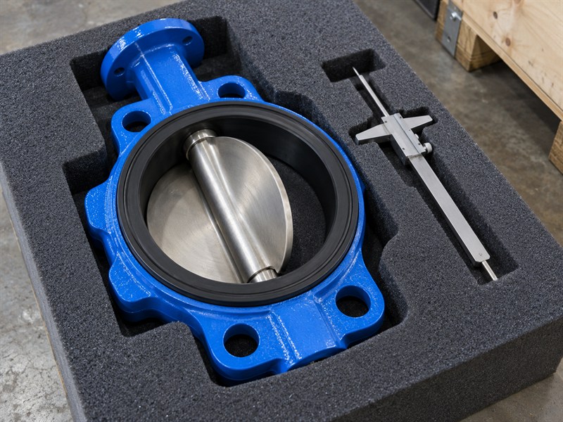
Face-to-face length in a JIS butterfly valve dimensions drawing is the axial distance between the defined valve end faces. Confirm its exact definition, value, and tolerance for the offered construction. Do not infer it from the flange pressure designation or a photograph of a similar valve.
Compare that length with the permitted installation arrangement between the mating flanges. Review the manufacturer's seat and gasket instructions as part of the assembly. Adding an unapproved gasket or spacer changes the connection and may affect seat compression, bolting, and disc clearance.
What should a replacement survey record?
Record the available space and its measurement conditions. Identify whether the piping is isolated, whether the old valve remains installed, and whether flange alignment or pipe movement affects the reading.
| Axial check | Required reference |
|---|---|
| Valve body length | Offered drawing and tolerance |
| Available space | Verified site geometry or controlled piping drawing |
| Assembly arrangement | Manufacturer's seat, gasket, and fastening requirements |
Use the wafer valve size guide to organize the comparison. Request a written resolution if the replacement drawing differs from the accepted installation space.
Distinguish face-to-face length from the thickness of a loose flange or the visible body edge in a photograph. Ask the supplier to mark the measurement endpoints on the drawing. That prevents the purchaser and factory from comparing different features while using the same short dimension label.
4. Which JIS butterfly valve dimensions define flange fit?
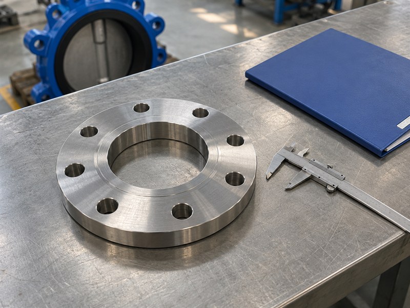
A JIS butterfly valve dimensions survey should record the mating flange’s standard, size, pressure designation, facing, relevant outside diameter, bolt-circle diameter, hole count, hole diameter, and bore. Keep the drawing values and measured values in separate columns. Record tolerances or acceptance references where the inspection requires them.
The flange interface and valve design route answer different questions. The scope of JIS B 2032:2024 concerns a particular wafer-type rubber-seated valve construction. The purchaser still needs the exact mating connection identified for the offered size and configuration.
Why should bolting receive its own review?
Fastener length, engagement, insertion access, and the permitted assembly arrangement depend on the selected valve and mating components. A hole pattern alone cannot specify the full fastener package.
| Flange feature | Reason for checking |
|---|---|
| Drilling geometry | Locates the permitted fasteners |
| Facing and bore | Defines contact and clearance conditions |
| Fastener arrangement | Defines engagement, access, and assembly method |
Use the butterfly valve bolt guide alongside the approved drawing. Do not redrill a delivered valve or flange to resolve an unapproved mismatch.
5. How do JIS butterfly valve dimensions affect disc clearance?
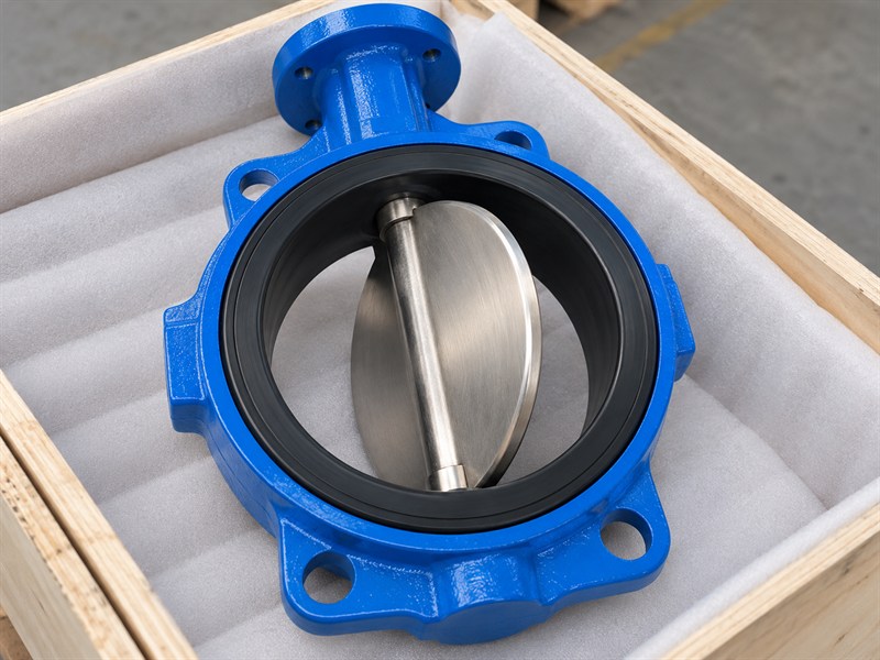
JIS butterfly valve dimensions must allow for the disc extending beyond the body’s end faces as it rotates. Review its swept envelope through the required operating travel against both mating bores and nearby equipment. A valve that enters the gap between flanges may still be unable to open fully.
Include liners, pipe-wall thickness, internal weld features, reducers, and adjacent fittings in the check. Ask the supplier for the minimum required clear bore and any installation restrictions. Do not estimate that clearance from nominal size or a general cross-section illustration.
What should happen when the bore is uncertain?
Mark the feature as unconfirmed and arrange a safe verification method. If the equipment remains in service, plan the necessary measurement during an approved isolation rather than presenting an estimate as a verified dimension.
| Clearance field | Required information |
|---|---|
| Disc envelope | Offered valve drawing and required travel |
| Mating bore | Actual flange, pipe, and lining geometry |
| Nearby obstruction | Distance and internal shape of adjacent components |
Resolve any interference before installation. Do not grind the disc, trim the seat, or adjust stops to make an unsuitable valve fit a restricted bore.
6. Which JIS butterfly valve dimensions affect operator access?
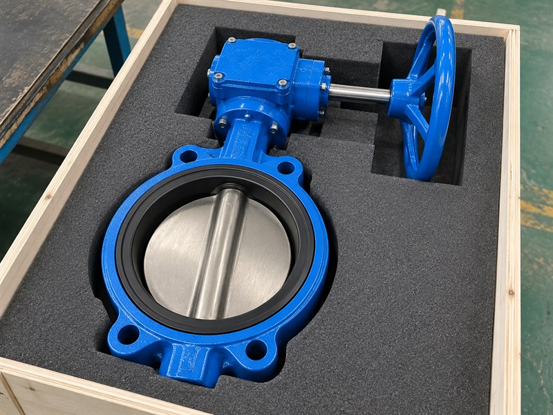
Include complete assembly height, width, drive orientation, and operating sweep in the JIS butterfly valve dimensions review. Include lever movement or handwheel access, actuator dimensions, solenoids, feedback devices, tubing connections, cable entries, and the space required to reach mounting fasteners.
Maintenance access can require more room than normal operation. A valve may open correctly while its operator cannot be removed without disturbing nearby pipework. Ask for the required service envelope when planning a replacement in a congested installation.
How should orientation be shown on the drawing?
Use the agreed pipeline and shaft references so the supplier and site team interpret the same view. Confirm the manufacturer's permitted butterfly valve orientation for the selected assembly.
| Envelope check | Site question |
|---|---|
| Operation | Can the lever, wheel, or actuator complete its travel? |
| Connections | Can tubing, wiring, and fasteners be installed? |
| Maintenance | Can service parts and the operator be accessed or removed? |
Record nearby supports, insulation, platforms, and branches in the survey. A cropped photograph of the valve alone can hide the obstruction that controls the replacement choice.
Include the space needed for a technician to reach and use the operator. A handwheel can clear the pipe geometrically while a nearby wall prevents practical access. Confirm the accepted operating position and any required platform or remote arrangement with the site team before freezing the assembly layout.
7. Which JIS butterfly valve dimensions define mounting fit?
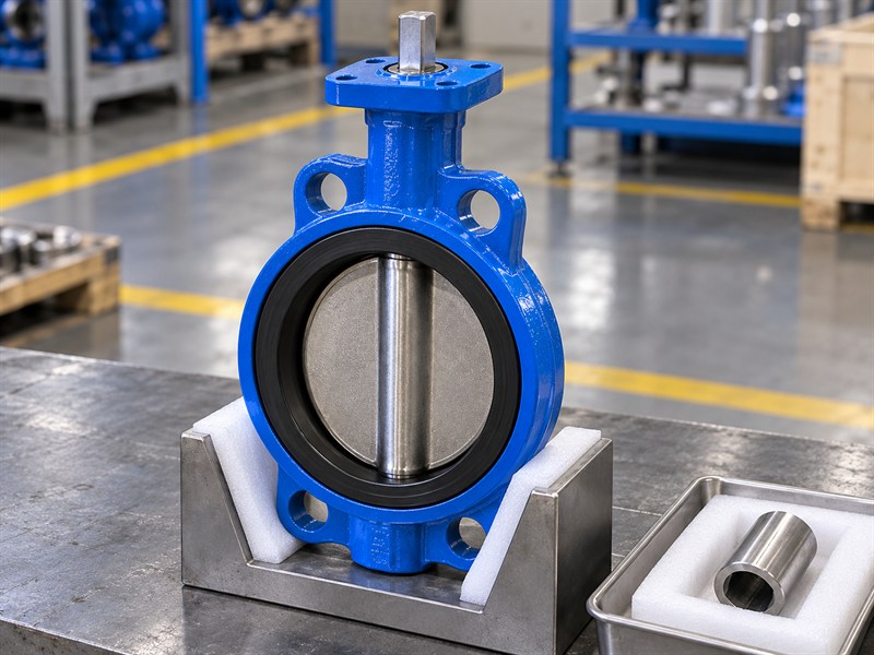
Record the mounting pattern, shaft form, drive dimensions, engagement, and coupling arrangement in the JIS butterfly valve dimensions package. Check how the actuator or gearbox connects to the valve, including any intermediate bracket. An operator that shares a mounting pattern can still have an unsuitable drive interface or load capacity.
ISO 5211:2026 addresses part-turn actuator attachment requirements, including interface and driving-component dimensions. Its published scope also addresses reference torque values. A mounting-standard label therefore needs a configuration-specific mechanical review; it cannot replace the complete assembly selection.
Which documents should be compared together?
Review the valve drawing, operator drawing, bracket and coupling details, and the actuator sizing basis. Keep dimensional fit and allowable mechanical loads as separate acceptance checks.
| Drive field | Confirmation needed |
|---|---|
| Mounting pattern | Agreed flange geometry and fastening |
| Shaft and coupling | Form, dimensions, engagement, and retention |
| Load path | Capacity of the assembled drive components |
Confirm the final disc position, stop arrangement, and indication after assembly. Avoid approving an operator substitution using its external size alone.
8. How should you record JIS butterfly valve dimensions?
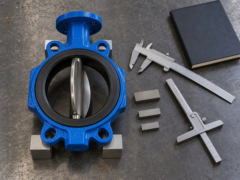
For JIS butterfly valve dimensions, record the measurement method, instrument, reference points, and conditions for every installation-critical value. Choose an instrument and method suitable for the required tolerance. A rough field survey and a final dimensional inspection may serve different purposes and should be identified accordingly.
Keep unmeasured features visible. If a flange bore, shaft detail, or concealed body length cannot be checked, identify the source of the provisional value and the person responsible for confirming it. Do not remove the uncertainty by copying a convenient catalogue number into the verified column.
What should a discrepancy record contain?
Include the required value, observed value, drawing reference, method, and location. Add photographs where they help identify the feature, and record the approved disposition separately from the observation.
| Record field | Purpose |
|---|---|
| Source and method | Explains how the value was obtained |
| Status | Distinguishes confirmed from provisional dimensions |
| Disposition | Records the accepted response to a conflict |
If a measurement changes after isolation or dismantling, return the revised data for review before releasing the replacement valve for installation.
Keep a record of the accepted change with the supplier's response. Update the worksheet, drawing list, and affected order attachment together so the receiving inspector can identify the approved arrangement.
9. How do you approve JIS butterfly valve dimensions for an order?
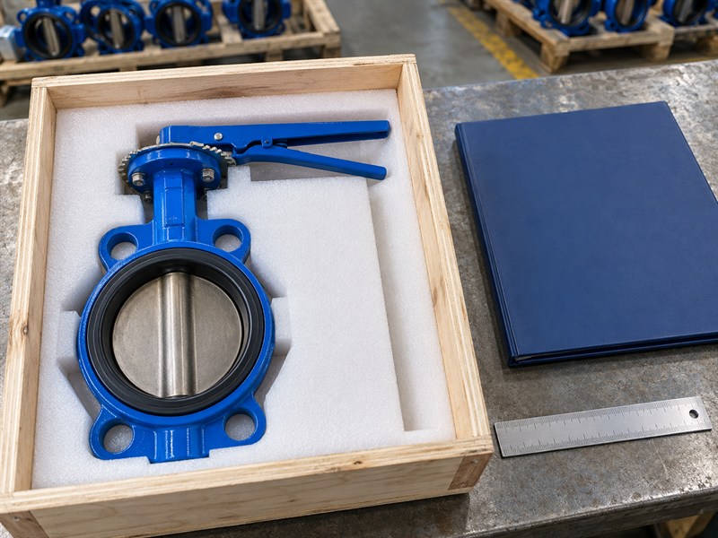
Approve a drawing package that covers the complete offered assembly and its installation interfaces. It should resolve the JIS butterfly valve dimensions that control fit, along with the materials, service limits, operator, and accepted exceptions needed to identify the actual order.
Ask the supplier to return a marked dimensional comparison if the valve replaces an existing product. Keep the old and new values distinguishable. A statement that the new valve is “equivalent” leaves the site team unable to identify which differences were reviewed and accepted.
Which changes should reopen the fit review?
Review changes to body construction, face-to-face length, flange drilling, disc profile, mounting, operator, and accessory position. A replacement seat arrangement may also affect installation instructions and the accepted assembly conditions.
| Approved attachment | What it controls |
|---|---|
| General arrangement | Complete assembly and access envelope |
| Interface drawing | Flange, bore, length, and drive details |
| Comparison and deviations | Accepted differences from the existing installation |
Send the completed worksheet and available site drawings when you contact RUITO for a review. Ask for confirmation of unresolved dimensions before placing the order.
10. What JIS butterfly valve dimensions questions do buyers ask?
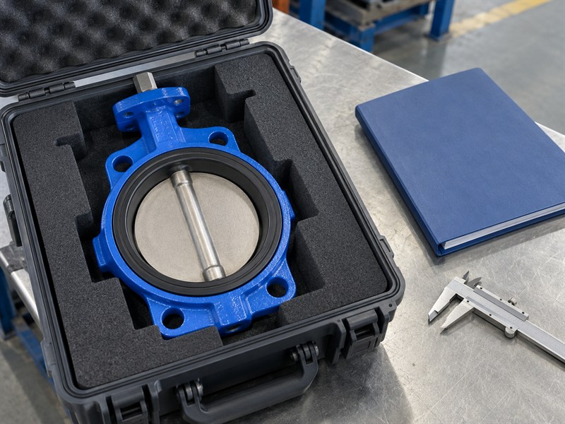
Q1: Can one chart cover every JIS butterfly valve?
No; JIS butterfly valve dimensions vary with the selected construction, connection, seat arrangement, and operator. Use the drawing for the exact offered configuration.
Q2: Does matching drilling prove full compatibility?
No. Check body length, facing requirements, fasteners, clear bore, disc sweep, service limits, and operator access. The bolt pattern addresses only part of the installation.
Q3: Is nominal size the actual internal diameter?
Use the actual component drawing for bore dimensions. The nominal-size designation does not establish every internal opening or the clearance available to the rotating disc.
Q4: Can a photograph provide the missing dimensions?
A photograph can identify construction and surrounding obstructions. Record installation-critical values using controlled drawings or suitable measurements, with clear reference points and any uncertainty identified.
Q5: What should I do if the replacement drawing differs?
List each difference and request a technical review against the installation. Obtain an approved disposition before manufacture or shipment. Do not rely on field modification to resolve an unreviewed dimensional conflict.