

A butterfly valve P&ID symbol is a standardized graphical representation used in piping and instrumentation diagrams to indicate the presence, orientation, and actuation of a quarter-turn rotary disc valve. Designing complex piping systems often leads to cluttered diagrams where improper valve selection causes severe operational failures. Misinterpreting a single symbol can result in restricted flow, pressure drops, or catastrophic system blowouts that halt production entirely. Fortunately, mastering the standard butterfly valve p&id drafting techniques allows you to design safe, efficient pipelines every time.
What Are Butterfly Valve P&ID Symbols?
Butterfly valve P&ID symbols are minimalist visual tools depicting a circle bisected by a line to represent the valve’s rotating disc mechanism. When you read a butterfly valve p&id drawing, you instantly recognize the quarter-turn functionality intended for flow isolation. These standard graphical marks help engineers coordinate layouts seamlessly without misinterpreting the piping components. You can rely on these shapes to communicate exact system configurations across different engineering departments.
What Do the Basic Shapes Mean?
The core elements of this drawing include the circular body and a diagonal line crossing through the center. Here is the deal, this exact shape prevents confusion by distinguishing itself from linear sliding valves.
- The circle represents the main housing body.
- The diagonal line signifies the internal rotating disc.
- Intersecting lines show specific pipeline connections.
Key Takeaway: Understanding these basic shapes guarantees you can identify flow control components quickly and accurately on any schematic.
| Element | Function | Application Context |
|---|---|---|
| Circle | Housing | Valve body identification |
| Line | Disc | Flow manipulation mechanism |
| Tags | Identification | Maintenance tracking tool |
This table clarifies how each graphical component translates directly to physical valve parts.
How Do You Compare Butterfly Valve P&ID Symbols With Others?
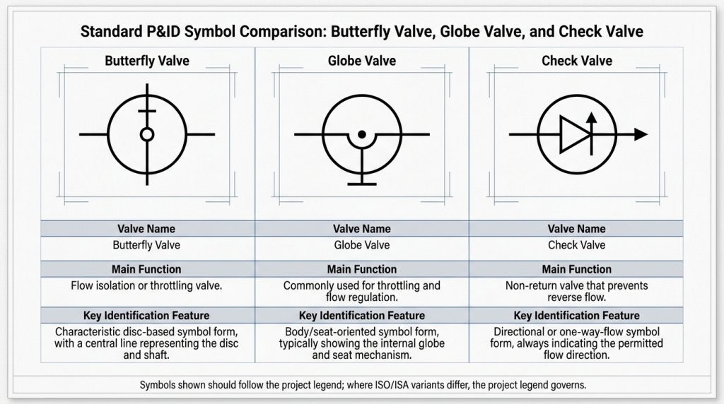
You compare butterfly valve P&ID symbols with others by analyzing the internal geometric elements that define their specific flow control mechanisms. A globe valve features a small inner circle, while the butterfly valve p&id drawing relies entirely on a single diagonal line. This stark contrast prevents engineers from confusing a quarter-turn shutoff mechanism with a linear throttling plug. You must memorize these visual differences to read engineering schematics fluently.
Can You Differentiate From Globe Valves?
Globe valves use an internal dot or secondary circle to show their sliding plug, while butterfly symbols stay minimal. You might be wondering, why does this slight visual difference matter so much in practical design?
- Globe symbols indicate precision throttling capabilities.
- Check symbols use an arrow for directional flow.
- Butterfly symbols highlight fast quarter-turn action.
Key Takeaway: Spotting the visual differences between these graphics helps you specify the correct valve for pressure regulation versus rapid shutoff.
| Valve Type | Symbol Mark | Primary Function |
|---|---|---|
| Butterfly | Diagonal line | Fast isolation |
| Globe | Inner dot | Fine throttling |
| Check | Inside arrow | Backflow prevention |
This table highlights the distinct visual markers used to separate different flow control mechanisms.
What Are the Different Types of Butterfly Valve P&ID Symbols?
Different types of butterfly valve P&ID symbols incorporate extra graphical tags to show manual, pneumatic, electric, or hydraulic actuation methods. Selecting the right butterfly valve p&id representation dictates how the system will be controlled during live operations. Manual versions simply add a small handwheel icon, while automated versions attach a square or semi-circle with specific lettering. You need to apply these modifier tags to convey the automation logic accurately.
How Are Actuators Represented?
Actuators appear as geometric extensions attached directly to the main valve body circle on the drawing. What is the real story behind these tiny letters and shapes?
- A semi-circle with a “P” means pneumatic control.
- A box with an “E” signifies electric motor actuation.
- A simple handwheel drawing means manual human operation.
Key Takeaway: Memorizing actuator modifiers allows you to recognize the automation strategy of the entire fluid network instantly.
| Actuator | Symbol Modifier | Operation Source |
|---|---|---|
| Manual | Handwheel | Human effort |
| Pneumatic | “P” mark | Air pressure |
| Electric | “E” mark | Motor drive |
This table summarizes the standard modifier tags used to denote various actuation methods.
How Can You Accurately Read the Butterfly Valve P&ID Symbol?
You accurately read the butterfly valve P&ID symbol by observing the orientation of the diagonal line relative to the main pipeline. If you notice a butterfly valve p&id showing the line parallel to the pipe, the valve is completely open. A perpendicular line indicates a closed position, stopping all media flow through that specific section. You use these orientation cues to trace active flow paths during system diagnostics.
Does Orientation Matter in Reading?
Orientation tells you the default operating state of the system before any automation takes over. Ready for the good part? You can use color fills to verify normal operating conditions at a single glance.
- Parallel lines show active flow paths.
- Perpendicular lines block the media route.
- Solid filled circles mean normally closed default states.
Key Takeaway: Interpreting the orientation and fill color accurately helps you determine the fail-safe status of the pipeline.
| State | Line Orientation | Flow Status |
|---|---|---|
| Open | Parallel | Media flows |
| Closed | Perpendicular | Media blocked |
| NC | Solid fill | Default closed |
This table demonstrates how line angles and shading communicate the functional state of the component.
Where Are Butterfly Valve P&ID Symbols Used in Applications?
Butterfly valve P&ID symbols are used in industrial applications ranging from municipal water treatment plants to high-pressure chemical processing facilities. When a butterfly valve p&id appears on a cooling tower schematic, it usually indicates a massive isolation point. These graphics map out HVAC networks, fire protection lines, and pharmaceutical mixing setups. You will find these specific drawings wherever large-volume media requires rapid quarter-turn control.
What Systems Rely on These Diagrams?
Massive fluid networks depend on these standardized drawings to plan maintenance routines and safety shutoffs. This is where it gets interesting, as different industries rely on the same universal symbols.
- Water plants use them for main line isolation.
- Chemical plants require them for hazardous media routing.
- HVAC systems depend on them for air and water balancing.
Key Takeaway: Recognizing these diagrams across varying industries proves the versatility and universal acceptance of this specific drafting standard.
| Industry | Primary Use | Media Handled |
|---|---|---|
| Water Treatment | Main isolation | Raw water |
| Chemical | Routing control | Corrosive fluids |
| HVAC | System balancing | Treated air |
This table outlines the primary applications and media types associated with these specific diagrams across different sectors.
What Are the Best Practices for Drafting Butterfly Valve P&ID Symbols?
The best practices for drafting butterfly valve P&ID symbols include using recognized ISO or ISA standards and maintaining strict tag consistency. Every time you sketch a butterfly valve p&id, you must attach a clear alphanumeric tag linking it to a master equipment list. Aligning your symbols with other project deliverables prevents costly procurement errors down the line. You should always include a detailed legend sheet to explain any custom modifications you make.
How Should You Standardize Tags?
Standardizing tags requires a unified naming convention that every department agrees upon before the project starts. Listen to this, keeping tags uniform is the single most effective way to eliminate confusion.
- Use prefix letters like “BV” for quick identification.
- Assign sequential numbers based on piping zones.
- Match the tag exactly on the bill of materials.
Key Takeaway: Consistent tagging bridges the gap between digital schematics and physical hardware procurement.
| Tag Element | Purpose | Benefit |
|---|---|---|
| Prefix | Valve type | Fast recognition |
| Number | Sequence location | Easy tracking |
| Suffix | Actuator type | Detail clarity |
This table breaks down a standard tagging format to streamline project documentation.
How Do You Avoid Common Butterfly Valve P&ID Mistakes?
You avoid common butterfly valve P&ID mistakes by strictly following the project legend and double-checking actuator specifications before finalizing the drawing. A poorly drafted butterfly valve p&id can easily look like a ball valve, causing contractors to install the wrong hardware. You must verify that the flow direction arrows and fail-safe modifiers match the intended process logic. Taking the time to review these specific details protects the system from critical operational failures.
Are Similar Symbols Confusing You?
Many rotational valves share similar circular boundaries that can blur together on dense technical layouts. Truth be told, skipping the legend review causes the majority of misinterpretations on site.
- Check the inner diagonal line carefully.
- Verify the actuation modifier block.
- Consult the legend for custom variations.
Key Takeaway: Double-checking the distinct diagonal line against the legend prevents catastrophic installation mix-ups.
| Mistake | Consequence | Prevention |
|---|---|---|
| Wrong symbol | Bad procurement | Legend review |
| Missing actuator | Manual operation only | Modifier check |
| Reversed NO/NC | System failure | Color fill verify |
This table lists frequent drafting errors and the corresponding methods to prevent them from happening.
Can You Automate Butterfly Valve P&ID Symbols in Design?
You can automate butterfly valve P&ID symbols in design by utilizing intelligent CAD software that links graphical icons directly to engineering databases. Modern software auto-populates the butterfly valve p&id tags and checks for drafting rule violations instantly. You merely drag and drop the standard block, and the program assigns the correct specifications based on the pipeline parameters. This digital integration speeds up the drafting process and drastically reduces human error.
What Software Tools Work Best?
Leading engineering platforms offer built-in libraries packed with standardized fluid control icons. Check this out, these smart tools update the bill of materials automatically when you change a single symbol.
- SmartPlant offers robust database linking.
- AutoCAD P&ID provides dynamic symbol scaling.
- Lucidchart allows rapid conceptual mapping.
Key Takeaway: Leveraging intelligent drafting software eliminates tedious manual updates and keeps your documentation perfectly synchronized.
| Software | Best Feature | Target User |
|---|---|---|
| SmartPlant | Deep database sync | Plant engineers |
| AutoCAD | Dynamic block libraries | Draftsmen |
| Lucidchart | Cloud collaboration | System planners |
This table compares popular drafting tools based on their primary features and target audiences.
Why Is Valve Orientation Critical in Butterfly Valve P&ID Drawings?
Valve orientation is critical in butterfly valve P&ID drawings because it dictates the fail-safe position and immediate flow status of the pipeline. If your butterfly valve p&id displays the wrong default state, the automation logic will misinterpret the system requirements. You must draw normally open and normally closed states accurately to secure emergency shutdown procedures. Precise orientation drafting guarantees that safety systems operate correctly during a power loss.
How Does Position Affect Flow?
The resting state of the disc dictates whether media passes freely or stops entirely during normal operations. Wait, there is more, getting this wrong can cause pumps to dead-head and rupture the pipes.
- Parallel lines allow full capacity flow.
- Perpendicular lines isolate the downstream equipment.
- Angled lines indicate a throttling position.
Key Takeaway: Accurate orientation drawing prevents catastrophic pressure buildup by ensuring correct baseline flow logic.
| Position | Result | Danger if wrong |
|---|---|---|
| Open | Free flow | Unintended flooding |
| Closed | Isolated flow | Pump cavitation |
| Throttle | Regulated flow | Pressure spikes |
This table outlines how the drawn position affects physical media movement and system safety.
How Do Butterfly Valve P&ID Symbols Impact System Maintenance?
Butterfly valve P&ID symbols impact system maintenance by providing technicians with an exact roadmap for safe pipeline isolation during repairs. When reading a butterfly valve p&id, maintenance crews know exactly which automated valves to lock out before servicing a pump. You rely on these precise schematic locations to drain specific fluid zones safely. Accurate documentation directly reduces downtime by eliminating guesswork on the factory floor.
Can Clear Diagrams Prevent Downtime?
Detailed schematics guide the repair team straight to the problem area without unnecessary delays. Let me explain, a clearly marked isolation point means the factory can keep other zones running smoothly.
- Accurate tags locate hardware instantly.
- Modifier blocks show how to override the actuator.
- Clear symbols prevent accidental wrong-valve shutoffs.
Key Takeaway: Providing crystal-clear schematics empowers your maintenance team to perform rapid, safe repairs with minimal production interruptions.
| Benefit | Action | Result |
|---|---|---|
| Fast location | Reading tags | Less searching |
| Safe lockout | Checking NO/NC | Zero accidents |
| Targeted repair | Tracing lines | Max uptime |
This table summarizes how accurate drafting directly translates to faster and safer physical maintenance work.
Final Thoughts
Mastering these standardized drawing practices prevents operational failures and speeds up your system maintenance protocols. Ruitoflow provides custom fluid control manufacturing solutions that perfectly match your rigorous engineering specifications. We manufacture industrial grade valves that integrate flawlessly into your most complex piping networks. Please contact our team today to discuss how we can supply the exact hardware required for your next project.
Frequently Asked Questions
Q1: Can I use a custom symbol for my diagrams?
You should not use custom symbols unless absolutely required by a specific client. Custom marks create confusion for outside contractors and increase the risk of installation errors during the build phase.
Q2: What’s the best way to show a pneumatic actuator?
The best way is to attach a semi-circle containing the letter “P” to the main body circle. This universally recognized modifier immediately alerts technicians that the unit requires a compressed air supply.
Q3: How do I know if the valve is normally open?
You can tell it is normally open if the main circular symbol is left unfilled or drawn with white space. Some engineers also add a distinct “NO” text tag next to the symbol for absolute clarity.
Q4: Can I differentiate a lug style from a wafer style on the drawing?
You usually cannot differentiate lug from wafer styles using the basic symbol alone. You must check the alphanumeric tag and cross-reference it with the bill of materials to determine the exact connection style.
Q5: What’s the best software for updating these diagrams?
Intelligent CAD platforms like AutoCAD P&ID are the best tools for updating these drawings. They automatically sync the graphical changes with your database, preventing mismatched information across your project files.