
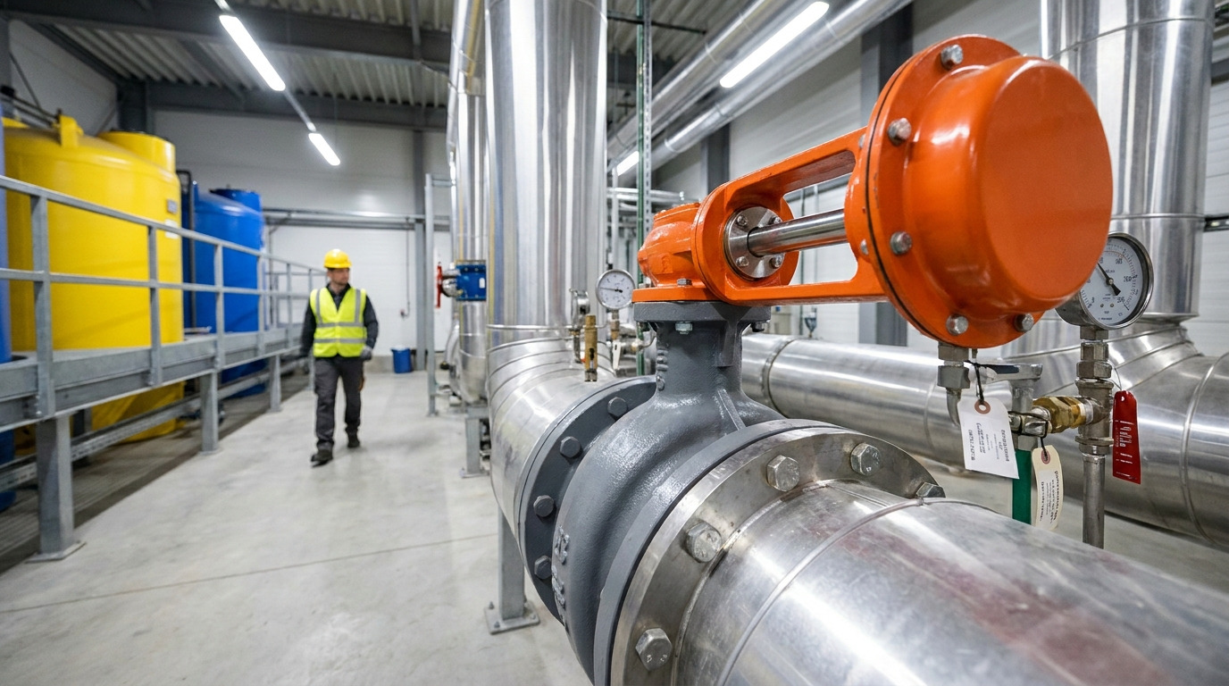
A robust butterfly valve stem serves as the foundational drive transmitter that regulates fluid flow, controls line pressure, and prevents hazardous system leaks. When this crucial component fails under intense operating pressure, your entire line suffers sudden pressure loss, expensive downtime, and severe mechanical damage. Our comprehensive engineering guide walks you through essential connection types, blowout safety mechanisms, and advanced metallurgy to ensure long-term piping reliability.
Why is a butterfly valve stem critical?
The butterfly valve stem is critical because it acts as the primary mechanical link transmitting rotational force from the actuator directly to the flow-control disc. This single axis of torque transmission determines whether your system can achieve tight shut-off and precise throttling.
How does shaft failure disrupt your line?
Think about it. When a valve shaft suffers structural failure mid-operation, the consequences ripple across your entire production line. You will experience immediate loss of pressure control and potential damage to expensive upstream equipment.
- Sudden loss of system pressure control.
- Ruined actuators due to sudden torque surges.
| Failure Mode | Prevention Strategy |
|---|---|
| Torsional Shearing | Correct diameter sizing |
| Surface Fatigue | Polished low-friction finishes |
This comparative data proves that proactive design engineering directly mitigates structural failure risks under high loads.
Key Takeaway: Prioritizing shaft torsional resistance prevents catastrophic structural shearing and secures continuous flow control.
How does a butterfly valve stem connect?
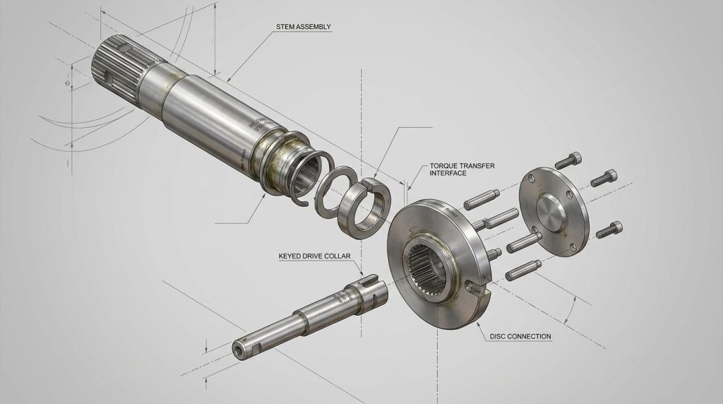
A butterfly valve stem connects to the disc using either pinned, splined, keyed, or double-D flat configurations to ensure precise mechanical drive transmission. Selecting the right connection type ensures that rotational torque is fully utilized without creating mechanical play.
Can you compare different connection joints?
Here is the deal. Each joint configuration is engineered to handle specific torque profiles and operating pressures. You must match the joint style directly to your process automation needs.
- Splined shafts for high-torque systems.
- Keyed joints for large-diameter lines.
| Joint Style | Backlash Risk |
|---|---|
| Splined | Minimum |
| Keyed | Medium |
This mechanical comparison shows that high-precision control loops depend heavily on zero-backlash connection designs.
Key Takeaway: Choosing a zero-backlash spline connection minimizes mechanical wear at the disc interface, guaranteeing precise control.
What keeps a butterfly valve stem in place?
The butterfly valve stem is kept firmly in place by thrust collars, retaining rings, and internal shoulders that prevent axial movement under line pressure. This robust physical retention keeps the internal components perfectly aligned during high-cycle actions.
What are the axial load retention methods?
Let’s look closer. Without a stable axial retention mechanism, internal pipeline pressures would force the shaft out of alignment. You can prevent this vertical drifting by selecting a design that uses heavy-duty retaining collar systems.
- Internal machined shoulders for maximum support.
- Low-friction thrust washers to reduce wear.
| Method | Thrust Capacity |
|---|---|
| Machined Shoulder | Extremely High |
| Split-Ring Collar | High |
This structural overview demonstrates that robust axial locking directly preserves the precise alignment between the disc and the elastomeric seat.
Key Takeaway: Solid axial retention guarantees that the disc remains perfectly centered, reducing rotational friction and extending seat life.
How does a butterfly valve stem seal work?
A butterfly valve stem seal works by compressing elastomeric packing rings or O-rings within a stuffing box to block escape pathways for internal media. This prevents process fluids from bypassing the valve shaft and escaping into the atmosphere.
O-ring or packing gland: which is better?
What is the catch? You must balance tight sealing integrity against the friction-induced torque that these seals inevitably introduce. Choosing the right sealing materials keeps the packing gland from degrading prematurely.
- Multi-ring PTFE packing for chemical systems.
- Viton O-rings for low-temperature applications.
| Seal Material | Temperature Limits |
|---|---|
| PTFE Packing | -50°C to 200°C |
| Viton O-Rings | -20°C to 200°C |
Testing various sealing materials proves that spring-loaded packing compensates for structural wear and thermal expansion without manual adjustments.
Key Takeaway: Implementing live-loaded packing designs prevents environmental fugitive emissions and decreases routine packing-gland maintenance.
Why prevent butterfly valve stem blowout?
You must prevent blowout of the butterfly valve stem to stop internal line pressure from violently ejecting the shaft from the valve body when the actuator is detached. This crucial safety standard protects your field maintenance technicians from serious bodily injury.
Which safety design stops shaft ejection?
Make no mistake. A sudden shaft blowout can cause severe personnel injuries and immediate fluid loss in pressurized systems. You should always opt for an internationally certified design to guarantee safety during operation.
- Integral bottom-entry shaft shoulders.
- Independent internal circlips.
| Safety Feature | Primary Benefit |
|---|---|
| Integral Shoulder | Absolute mechanical lock |
| External Gland Plate | Secondary security |
Assessing these safety architectures demonstrates that body-retained integral shoulders offer the highest level of mechanical safety.
Key Takeaway: Specifying an internationally certified blowout-proof design protects your field operators during live actuator swaps and routine maintenance.
How to size a butterfly valve stem drive?
You size a butterfly valve stem drive by matching the connection geometry—such as square, double-D, or keyed profiles—to standard industrial actuator interfaces. Proper sizing ensures that operating torque is transferred smoothly without structural deformation of the shaft drive ends.
Are ISO 5211 standards essential for sizing?
Think about it. Using non-standard dimensions makes matching actuators unnecessarily difficult and leads to mechanical misalignment or shaft failure. You can ensure trouble-free integration by adhering to recognized international sizing specifications.
- Standardized torque ratings for secure fits.
- Direct-drive square shafts to eliminate brackets.
| Connection Type | Torque Distribution |
|---|---|
| Square Drive | High |
| Double-D Flat | Moderate |
Evaluating standard mounting interfaces proves that direct-mount square drives drastically reduce system complexity and mechanical backlash.
Key Takeaway: Standardizing on ISO 5211 drive profiles ensures hassle-free actuator upgrades and eliminates premature shaft wear.
Which butterfly valve stem metal is best?
The best alloy for a butterfly valve stem is selected based on a balance of mechanical tensile strength, torsional yield resistance, and chemical compatibility with the flowing medium. Selecting high-yield alloys prevents the shaft from twisting or snapping under high differential pressures.
Does duplex steel outperform standard metals?
Here is the truth. Standard stainless steels like 304 or 316 often lack the torsional strength required for high-pressure systems. You must match your metallurgy to both your chemical environment and peak torque loads.
- Duplex 2205 for marine environments.
- 17-4 PH steel for high tensile strength.
| Alloy Grade | Tensile Strength (MPa) |
|---|---|
| 17-4 PH | 1100 |
| Duplex 2205 | 655 |
Comparing metallurgy data shows that while standard stainless steel serves general applications well, high-pressure networks require high-yield alloys like 17-4 PH.
Key Takeaway: Choosing high-yield, corrosion-resistant alloys prevents shaft twisting under high-pressure differential loads.
How to fix a butterfly valve stem seizure?
You can fix a butterfly valve stem seizure by disassembling the packing gland, flushing out chemical scaling, and applying low-friction graphite lubricants to the bearing bushings. Addressing these mechanical binds quickly restores smooth rotary operation.
What are the key diagnostic steps for galling?
You see. Forcing a stuck valve open with a larger actuator can shear the drive mechanism or destroy the seat entirely. You should carefully inspect the contact points for evidence of metallic galling or severe corrosion build-up.
- Clean packing boxes with penetrating solvents.
- Inspect guide bushings for physical score marks.
| Seizure Cause | Primary Solution |
|---|---|
| Debris Build-up | Flush with solvent and lubricate |
| Metal Galling | Replace shaft and bushing metals |
Conducting a methodical mechanical check ensures you address the physical friction source without damaging the internal parts.
Key Takeaway: Periodic bushing flushing and proper gland adjustments prevent metal-on-metal galling, keeping your valve operating smoothly.
What causes butterfly valve stem deflection?
Dynamic fluid force is what causes butterfly valve stem deflection, pushing the shaft out of its true concentric centerline during throttling phases. This dynamic bending moment is particularly aggressive in high-velocity liquid lines.
How do high fluid velocities bend the shaft?
Surprisingly, when a valve throttles fluid at high velocities, the asymmetric flow patterns create a continuous bending moment on the disc. You will notice accelerated seat wear and packing leaks if the shaft is allowed to deflect.
- Uneven contact between disc and seat.
- Accelerated wear on guide bushings.
| Velocity Level | Deflection Risk |
|---|---|
| Low (< 2 m/s) | Negligible |
| High (> 5 m/s) | High |
Modeling fluid dynamics confirms that double-offset or triple-offset designs significantly reduce unbalanced lateral forces on the shaft during throttling.
Key Takeaway: Sizing over-sized shafts or upgrading to offset valve styles minimizes flow-induced deflection, securing tight shut-off.
When to replace a butterfly valve stem?
You must replace a butterfly valve stem when you observe permanent rotational twisting, deep mechanical wear patterns, or localized pitting corrosion during scheduled maintenance. Reusing a compromised shaft under high system pressures invites sudden and catastrophic mechanical failure.
How do you spot fatigue wear before failure?
As you know, micro-cracks and structural fatigue are often invisible to the naked eye until a catastrophic failure occurs. You must employ non-destructive testing methods during regular maintenance outages to find these hidden defects.
- Surface scoring along the seal contact areas.
- Distorted keyways or twisted spline teeth.
| Wear Symptom | Recommended Action |
|---|---|
| Spline Twist | Replace stem immediately |
| Gland Scoring | Refurbish or replace stem |
Implementing strict non-destructive testing protocols ensures compromised components are safely decommissioned before they fail under pressure.
Key Takeaway: Replacing worn-out shafts before they deform eliminates unexpected production delays and ensures full operational safety.
Optimize Your System with High-Performance Valve Stems
Say goodbye to unexpected downtime, sheared stems, and hazardous process leaks by upgrading your flow control infrastructure with our heavy-duty industrial valve solutions. We are committed to engineering robust, high-performance flow systems that secure your plant’s operational safety and maximize productivity. To find the perfect custom solution designed for your facility’s exact requirements, contact us today to collaborate with our expert application engineering team.
FAQ
Can I use standard stainless steel stems for high-pressure seawater systems?
No, standard stainless steel will corrode quickly in saltwater. You must use duplex 2205 or super-duplex alloys to prevent aggressive pitting and crevice corrosion under high mechanical stress.
What’s the best design to prevent a sudden blowout?
The best option is an integral, body-retained bottom shoulder. This configuration physically prevents the shaft from exiting the valve body even if the actuator is completely removed under line pressure.
Can I replace a twisted stem without replacing the entire valve?
Yes, you can replace a twisted shaft individually during a scheduled maintenance shutdown. However, you must carefully inspect the guide bushings and seat elastomer for secondary wear before returning the valve to service.
How do I know if my valve stem is sizing correctly?
Verify that your shaft’s maximum torque rating exceeds your actuator’s peak output torque by at least 30 percent. Always select standard ISO 5211 drive profiles to guarantee a precise, secure physical fit.