
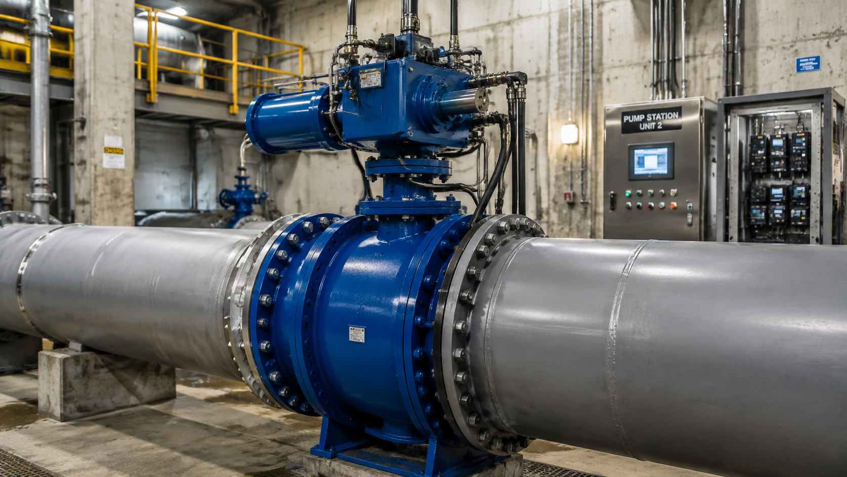
A hydraulic butterfly valve uses pressurized fluid to rotate a butterfly disc, giving you rapid, controlled pipeline isolation or throttling with high torque. A pump-station valve that closes too quickly can trigger pressure surges, while a weak actuator may stall against differential pressure and leave your process exposed. Correct hydraulic actuation addresses both risks through controlled travel, adjustable speed, and a defined fail-safe action. This article explains how that system works, where its benefits come from, and what you should specify before purchasing.
What Is a Hydraulic Butterfly Valve?
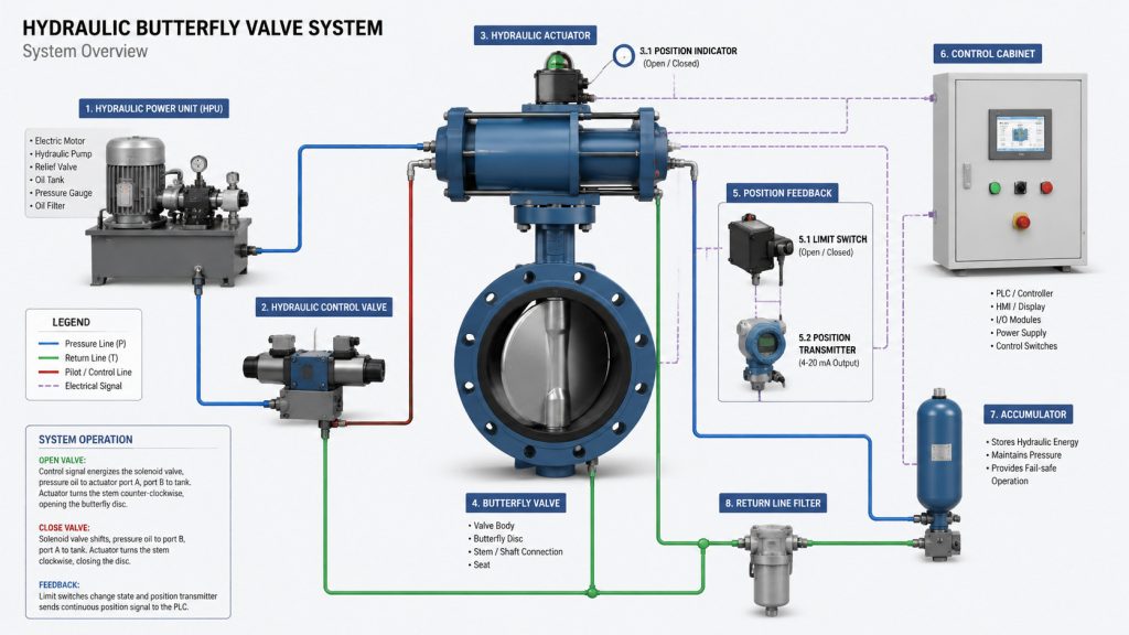
A hydraulic butterfly valve is a quarter-turn valve whose actuator converts hydraulic pressure into disc rotation. You gain automated flow control without relying on manual gear operation, making this arrangement suitable for large diameters, high torque, remote stations, and emergency shutdown duties.
Which parts form the complete valve package?
Start with the mechanical chain: each part transfers force or verifies position, so one weak interface can affect every operating command. Your package should cover more than a body and actuator; it also needs suitable controls, feedback, tubing, and stored-energy provisions where required.
- Valve body, disc, stem, seat, and bearings handle process fluid.
- A hydraulic cylinder or rotary actuator creates operating torque.
- A power unit supplies pressurized oil at controlled flow.
- Solenoid valves, limit switches, and a positioner manage movement.
- An accumulator can provide emergency motion after power loss.
| Element | Primary job | Specification check |
|---|---|---|
| Disc and seat | Control flow and shutoff | Media, temperature, leakage class |
| Actuator | Rotate disc through 90 degrees | Required torque and stroke time |
| Hydraulic unit | Supply pressure and flow | Duty cycle and oil cleanliness |
| Controls | Command and confirm position | Voltage, signals, and fail action |
This breakdown shows why actuator selection must follow valve torque data.
Key Takeaway: You can reduce interface failures by purchasing and reviewing the valve, actuator, controls, and feedback as one engineered package.
How Does a Hydraulic Butterfly Valve Work?
A hydraulic butterfly valve works by routing pressurized oil into an actuator, which turns its stem and disc through as much as 90 degrees. A disc parallel with process flow represents the open position, while a perpendicular disc blocks flow at the closed position.
What happens during opening, throttling, and closing?
Oil enters one actuator chamber while oil from another chamber returns to the reservoir. Here is where control becomes useful: a directional valve selects movement, while flow controls set travel speed and a positioner can stop the disc at a commanded angle.
- Opening pressure creates torque that unseats and rotates the disc.
- Metered oil flow limits acceleration and operating speed.
- Position feedback compares actual travel with each command.
- Reversed oil flow closes the valve under hydraulic force.
- Relief valves protect the circuit against excess pressure.
| Operating state | Disc position | Hydraulic action | Process result |
|---|---|---|---|
| Open | Near 90 degrees | Actuator reaches open stop | High flow capacity |
| Modulating | Between stops | Positioner meters oil | Controlled flow |
| Closed | Near 0 degrees | Actuator seats disc | Pipeline isolation |
| Fail-safe | Preset position | Accumulator or spring acts | Defined safe response |
The sequence makes closing behavior adjustable rather than abrupt.
Key Takeaway: You can protect both process control and piping by defining travel time, stop positions, and failure response before commissioning.
Which Components Control a Hydraulic Butterfly Valve?
A hydraulic butterfly valve is controlled by its hydraulic power unit, directional valves, flow controls, actuator, sensors, and control logic. These components determine available torque, response speed, positioning accuracy, and behavior during a power or signal failure.
How does each control layer affect reliability?
A useful detail: pressure creates force, yet oil flow sets speed and control logic decides direction. You should treat pressure, flow, cleanliness, feedback, and emergency energy as separate design checks rather than one actuator rating.
- Pump capacity must support required pressure at operating flow.
- Filtration protects servo and directional valve clearances.
- Throttle or proportional valves regulate acceleration and speed.
- Limit switches confirm fully open and fully closed positions.
- Pressure switches can detect overloads or supply loss.
| Control layer | Main variable | Typical failure symptom |
|---|---|---|
| Power unit | Pressure and flow | Slow travel or actuator stall |
| Oil circuit | Cleanliness and leakage | Erratic motion or drift |
| Feedback | Position signal | False status or poor modulation |
| Logic | Sequence and interlocks | Unsafe or mistimed operation |
This view separates hydraulic faults from valve friction problems.
Key Takeaway: You can diagnose faster when commissioning records include baseline pressure, travel time, torque demand, and position feedback.
Why Does a Hydraulic Butterfly Valve Offer Wide Control?
A hydraulic butterfly valve offers a broad operating range because hydraulic flow can move and hold its disc at controlled angles. That capability supports on-off service plus moderate throttling, provided you size the valve from its Cv curve instead of matching pipe diameter alone.
How can you maintain stable modulation?
Flow change is nonlinear across disc travel, so equal angle changes do not produce equal flow changes. What does that mean for you? Stable control usually comes from selecting a working range that avoids prolonged operation near the seat and avoids an oversized valve.
- Review minimum, normal, and maximum flow conditions.
- Compare required Cv with manufacturer data at several angles.
- Check velocity, cavitation, noise, and pressure recovery.
- Keep normal control away from nearly closed positions.
- Use a suitable positioner for repeatable partial travel.
| Design question | Risk if ignored | Practical check |
|---|---|---|
| Is Cv matched to demand? | Sensitive or weak control | Plot three flow cases |
| Is pressure drop acceptable? | Energy loss or cavitation | Calculate each load point |
| Can actuator hold position? | Drift and oscillation | Verify hydraulic lock and feedback |
| Is disc angle suitable? | Seat wear and turbulence | Review expected travel band |
The operating band matters more than a single rated Cv value.
Key Takeaway: You can gain usable control range by sizing around real load cases and verifying disc position across them.
Why Is Hydraulic Butterfly Valve Response So Fast?
A hydraulic butterfly valve responds quickly because incompressible oil transfers force efficiently and the disc needs only quarter-turn travel. High power density lets a compact actuator move large valves faster than many multi-turn arrangements while still allowing controlled deceleration.
When should fast movement be slowed down?
Fast travel helps emergency isolation, yet an aggressive closing profile can cause water hammer, pipe movement, or pump upset. Here is the balancing act: use speed where safety demands it, then meter the final portion of travel to limit pressure transients.
- Set opening time around pump and process sequencing.
- Use staged closing for long water pipelines where appropriate.
- Add cushioning near end stops to reduce mechanical shock.
- Confirm accumulator capacity at minimum stored pressure.
- Test fail-safe travel under maximum differential pressure.
| Response feature | Benefit | Design caution |
|---|---|---|
| High hydraulic torque | Rapid breakaway | Size for peak seat torque |
| Adjustable oil flow | Tunable stroke time | Avoid unstable restriction |
| Accumulator energy | Motion after power loss | Check usable oil volume |
| End cushioning | Softer stop | Confirm full seat engagement |
Fast response becomes safer when its profile matches system dynamics.
Key Takeaway: You can combine emergency speed with surge control by specifying staged motion and testing actual closure under operating conditions.
How Does Simple Hydraulic Butterfly Valve Design Cut Maintenance?
A hydraulic butterfly valve reduces valve-side maintenance through a compact body, few moving flow-path parts, and 90-degree motion. Maintenance still covers hydraulic oil, seals, filters, tubing, sensors, and actuator linkages, so simplicity does not remove planned inspection.
What should your maintenance routine cover?
The practical point is simple: trend small changes before they become shutdowns. Rising travel time, drifting position, hotter oil, external seepage, or higher breakaway pressure can reveal contamination, friction, or seal wear early.
- Inspect tubing, fittings, actuator seals, and stem area for leaks.
- Record opening and closing times under comparable conditions.
- Check oil level, condition, temperature, and filter indication.
- Exercise standby valves and verify every limit switch.
- Compare seat leakage with specified acceptance criteria.
| Inspection item | Warning sign | Likely area to check |
|---|---|---|
| Travel time | Gradual increase | Filter, pump, friction, or restriction |
| Position holding | Disc drift | Internal actuator or valve leakage |
| Oil condition | Cloudy or dark fluid | Water, heat, or contamination |
| Seat tightness | Rising leakage | Seat, disc edge, or alignment |
Trend data helps you plan work during scheduled outages.
Key Takeaway: You can lower unplanned maintenance by recording repeatable performance indicators instead of relying only on visual checks.
Why Can a Hydraulic Butterfly Valve Lower Ownership Cost?
A hydraulic butterfly valve can lower ownership cost through compact piping dimensions, low valve mass, quick actuation, and accessible wearing parts. Savings depend on correct materials and sizing because a cheap but mismatched seat, actuator, or control package can erase purchase-price gains.
Which costs belong in your comparison?
Purchase price tells only part of a B2B procurement story. The real cost appears later: engineering revisions, mounting hardware, hydraulic power, spare seals, labor, downtime, testing, documentation, and service support all shape lifecycle value.
- Compare installed cost rather than valve price alone.
- Include actuator, power unit, controls, and cabling or tubing.
- Estimate energy use from pressure drop and hydraulic duty.
- Review spare-part access and replacement procedures.
- Assign a cost to planned and unplanned downtime.
| Cost category | Lower-cost driver | Potential cost penalty |
|---|---|---|
| Installation | Short face-to-face body | Flange or actuator mismatch |
| Operation | Low pressure loss when sized well | Oversizing or throttling near closed |
| Maintenance | Replaceable seat and simple disc | Dirty oil or unavailable seals |
| Downtime | Fast actuation and diagnostics | Weak documentation or support |
Lifecycle comparison prevents low bids from hiding downstream expense.
Key Takeaway: You can make a stronger sourcing decision by comparing installed, operating, maintenance, and downtime costs across the planned service period.
How Does a Hydraulic Butterfly Valve Limit Pressure Loss?
A hydraulic butterfly valve limits pressure loss through a short body and relatively open flow path when its disc approaches full open. The disc remains inside the pipe, so pressure drop never disappears and rises sharply as the valve closes.
How should you check energy performance?
Use manufacturer Cv or Kv data at each expected angle, then calculate loss for actual flow and fluid density. Here is the catch: a valve selected only for line size may run at a poor angle, creating avoidable pump demand, noise, and unstable control.
- Calculate loss at minimum, normal, and peak flow.
- Use angle-specific Cv or Kv rather than a fully open value.
- Check fittings and straight-pipe conditions near the valve.
- Review cavitation margin for liquids with large pressure drops.
- Compare annual pumping energy across candidate sizes.
| Disc condition | Relative resistance | Operating implication |
|---|---|---|
| Fully open | Low | Best capacity and lower pump load |
| Moderately open | Medium | Useful throttling with verified data |
| Nearly closed | High | Noise, wear, and control sensitivity |
| Closed | Maximum | Isolation subject to leakage rating |
Angle-specific calculations reveal where energy loss actually occurs.
Key Takeaway: You can reduce pumping cost and control problems by checking pressure drop across the complete operating range.
Where Does a Hydraulic Butterfly Valve Perform Best?
A hydraulic butterfly valve performs best in large-diameter water, power, cooling, marine, mining, and general process lines requiring high torque or stored-energy closure. It suits pump discharge, penstock, emergency isolation, and remote duty where controlled speed matters.
Which service conditions shape the design?
Application fit depends on fluid chemistry, solids, temperature, pressure, cycling, and shutdown philosophy. This is the decision point: select body, disc, seat, offset geometry, and hydraulic controls from service data rather than using one standard build everywhere.
- Water networks may need staged closure against surge.
- Power plants may require remote isolation and interlocks.
- Marine systems need corrosion-resistant wetted materials.
- Mining lines need erosion review for solids and slurry.
- Chemical service demands verified seal and alloy compatibility.
| Service | Main demand | Common design response |
|---|---|---|
| Pump station | Surge control | Adjustable or two-stage closure |
| Cooling water | Frequent remote operation | Position feedback and durable soft seat |
| Hydropower | High torque and stored energy | Accumulator-backed actuator |
| Corrosive process | Material compatibility | Resistant disc, seat, and lining |
Each service changes both valve construction and control philosophy.
Key Takeaway: You can avoid premature failure by turning operating data into a duty-specific material, torque, and fail-action specification.
How Should You Specify a Hydraulic Butterfly Valve?
A hydraulic butterfly valve should be specified from process conditions, valve standards, torque demand, hydraulic supply, travel profile, leakage target, and failure position. A clear data sheet gives suppliers one performance basis and makes technical bids easier to compare.
What data should you send with an inquiry?
Before you request pricing: define normal and worst-case conditions, because actuator size follows peak differential pressure rather than nominal pipe pressure alone. Ask for drawings, torque calculations, Cv data, material certificates, pressure-test records, hydraulic schematics, and a documented functional test.
- State media, solids, concentration, temperature, and flow range.
- Provide valve size, pressure class, flange standard, and orientation.
- Define leakage class, bidirectional duty, and maximum differential pressure.
- Set opening time, closing profile, fail position, and cycle rate.
- List power, signal, feedback, hazardous-area, and documentation needs.
| Data group | Minimum input | Supplier output |
|---|---|---|
| Process | Media, flow, pressure, temperature | Materials and valve sizing |
| Mechanical | Size, flanges, layout, orientation | Drawing and mass data |
| Actuation | Torque, timing, fail action | Actuator and hydraulic sizing |
| Quality | Standards and inspection scope | Certificates and test plan |
A complete inquiry exposes exceptions before purchase-order release.
Key Takeaway: You can reduce rework and bid ambiguity by issuing one duty-based specification with defined acceptance documents.
What Should You Take Away Before Choosing?
A hydraulic actuation package can give you high torque, fast response, controlled travel, broad positioning, and dependable emergency action, while a butterfly body keeps installation compact. This article addressed operating sequence, control components, modulation, response, maintenance, cost, pressure loss, applications, and purchase data so you can judge a complete system rather than a valve alone.
For a duty-based review of materials, sizing, actuation, testing, and documentation, contact us today with your operating conditions. We help you turn project data into a practical valve package built for predictable control and long service; our position is clear: dependable flow control begins with engineering evidence, not catalog shortcuts.
FAQ
Can I use a hydraulic butterfly valve for throttling?
Yes, for moderate control duties. Check angle-specific Cv data, avoid sustained operation near closed, and use position feedback suited to your required accuracy.
What’s the best fail-safe position for my system?
It depends on process risk. Choose fail-close, fail-open, or fail-in-place through a hazard review covering power loss, surge, pump behavior, and downstream consequences.
How do I know if my hydraulic actuator is large enough?
Verify its available torque at minimum hydraulic pressure. That value must exceed maximum required valve torque at worst differential pressure with an agreed design margin.
Can I operate the valve after electrical power fails?
Yes, if stored hydraulic energy or another approved backup drives the required stroke. Confirm accumulator volume, minimum pressure, leakage allowance, and repeated-stroke needs through testing.
How do I know if closing speed may cause water hammer?
Check through surge analysis or measured transient data. Long lines, high velocity, pump trips, and rapid final closure can create harmful pressure changes that need staged timing.